Every lesson in this course focused on one or two peripherals at a time. Real products never work that way. A commercial sensor node reads multiple sensors on a shared bus, logs data to storage, updates a display, streams wirelessly, and triggers alarms, all running concurrently on a single microcontroller. This capstone builds exactly that system. You will integrate the BME280 environmental sensor, SSD1306 OLED display, microSD card, HC-05 Bluetooth module, potentiometer, relay, buzzer, LEDs, and push buttons into one cohesive data logger with a state machine UI. #STM32 #Capstone #DataLogger
What We Are Building
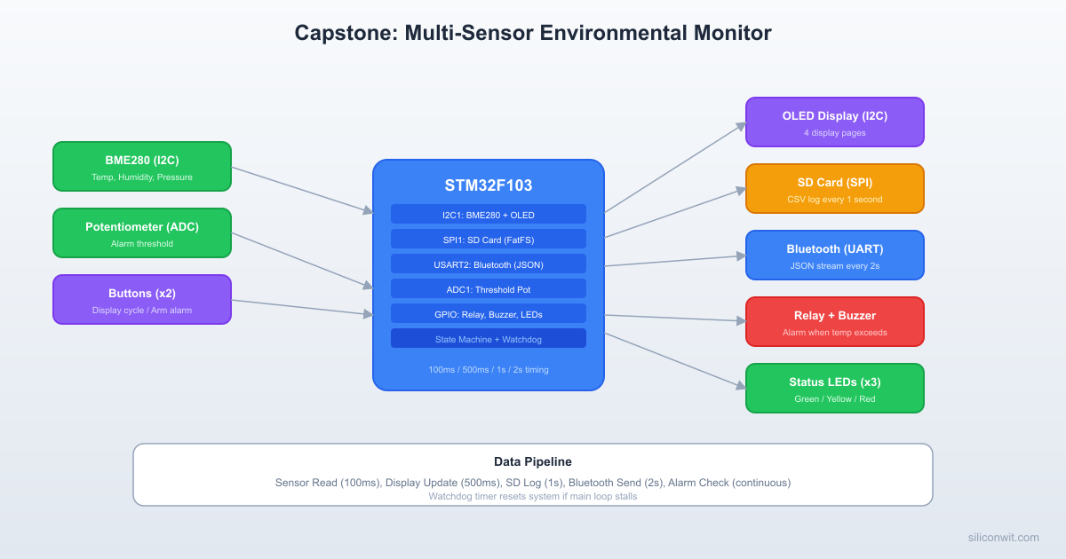
Environmental Monitoring Station
A standalone data acquisition system that reads temperature, humidity, and pressure from a BME280 sensor every 100 ms. The OLED display updates every 500 ms showing live readings and alarm threshold. The system logs CSV data to an SD card every second and streams JSON over Bluetooth every 2 seconds. A potentiometer sets the temperature alarm threshold. When temperature exceeds the threshold, a relay activates and a buzzer sounds an alarm pattern. Two push buttons cycle display pages and arm/disarm the alarm. Status LEDs indicate system state: green for normal, yellow for warning, red for alarm.
System overview:
Subsystem
Peripheral
Bus
Update Rate
Temperature, humidity, pressure
BME280
I2C1 (PB6/PB7)
100 ms
Display
SSD1306 OLED 128x64
I2C1 (PB6/PB7)
500 ms
Data storage
microSD card module
SPI1 (PA5/PA6/PA7, CS=PA4)
1 s
Wireless
HC-05 Bluetooth
USART2 (PA2/PA3)
2 s
Threshold input
10K potentiometer
ADC1 (PA0)
100 ms
Alarm output
Relay module
GPIO (PB12)
On threshold
Audio alarm
Passive buzzer
GPIO (PB13)
On threshold
User input
2x push buttons
GPIO (PB0, PB1)
Polled
Status
3x LEDs (green, yellow, red)
GPIO (PB14, PB15, PA8)
Continuous
Parts List
All parts are reused from previous lessons in this course.
Part
From Lesson
Bus/Pin
Blue Pill (STM32F103C8T6)
Lesson 1
N/A
ST-Link V2 clone
Lesson 1
SWD
BME280 module (I2C)
Lesson 4
I2C1
SSD1306 OLED 128x64 (I2C)
Lesson 4
I2C1
microSD card module
Lesson 5
SPI1
microSD card
Lesson 5
SPI1
HC-05 Bluetooth module
Lesson 6
USART2
10K potentiometer
Lesson 2
ADC1
Relay module (5V, 1-channel)
Lesson 1
GPIO
Passive buzzer
Lesson 1
GPIO
Push buttons (x2)
Lesson 1
GPIO
LEDs (green, yellow, red)
Various
GPIO
330 ohm resistors (x3)
Various
LED current limiting
4.7K resistors (x2)
Lesson 4
I2C pull-ups
Breadboard
Lesson 1
N/A
Jumper wires
Lesson 1
N/A
System Architecture
Bus Allocation
The STM32F103C8T6 has limited peripherals, so bus assignment requires planning. The key constraint is that I2C1 is shared between the BME280 and OLED, meaning these two devices must be accessed sequentially (never simultaneously).
Multi-Sensor System Architecture
┌──────────────────────────────────────┐
│ Blue Pill (STM32F103) │
│ │
│ I2C1 ──┬── BME280 (0x76) │
│ PB6/7 └── SSD1306 OLED (0x3C) │
│ │
│ SPI1 ───── microSD (CS=PA4) │
│ PA5/6/7 │
│ │
│ USART2 ─── HC-05 Bluetooth │
│ PA2/3 (JSON to phone) │
│ │
│ ADC1 ───── Potentiometer (PA0) │
│ (alarm threshold) │
│ │
│ GPIO ──┬── Relay (PB12) │
│ ├── Buzzer (PB13) │
│ ├── LEDs: G/Y/R │
│ └── Buttons x2 │
└──────────────────────────────────────┘
Bus
Devices
Clock Speed
Notes
I2C1 (PB6 SCL, PB7 SDA)
BME280 (0x76), SSD1306 (0x3C)
400 kHz
Different addresses, sequential access
SPI1 (PA5 SCK, PA6 MISO, PA7 MOSI)
microSD card (CS = PA4)
18 MHz max
Single device, dedicated CS
USART2 (PA2 TX, PA3 RX)
HC-05 Bluetooth
9600 baud
Default HC-05 baud rate
ADC1 (PA0)
Potentiometer
N/A
Single channel, polling
Timing Architecture
Different subsystems update at different rates. A simple tick counter in the main loop handles this without needing a real-time OS.
 Cooperative Scheduling Timeline Time (ms)  0   100  200  300  400  500            |    |    |    |    |    | Sensor     *----*----*----*----*----*-- (100 ms)
 OLED                            *-- (500 ms)
 SD card                              * (1000 ms)
 Bluetooth                            . (2000 ms)
 Alarm      *----*----*----*----*----*-- (100 ms)
 Buttons    *-*-*-*-*-*-*-*-*-*-*-*-*- (10 ms)
Task
Interval
Priority
Sensor read (BME280 + ADC)
100 ms
High
Display update (OLED)
500 ms
Medium
SD card write (CSV)
1000 ms
Medium
Bluetooth send (JSON)
2000 ms
Low
Button poll
10 ms
High
Alarm check
100 ms
High
Complete Wiring Table
Blue Pill Pin
Connects To
Function
PB6
BME280 SCL, OLED SCL
I2C1 SCL (4.7K pull-up to 3.3V)
PB7
BME280 SDA, OLED SDA
I2C1 SDA (4.7K pull-up to 3.3V)
PA5
SD card SCK
SPI1 SCK
PA6
SD card MISO
SPI1 MISO
PA7
SD card MOSI
SPI1 MOSI
PA4
SD card CS
SPI1 NSS (GPIO output)
PA2
HC-05 RXD
USART2 TX
PA3
HC-05 TXD
USART2 RX
PA0
Potentiometer wiper
ADC1 Channel 0
PB12
Relay module IN
Alarm relay control
PB13
Buzzer (+)
Alarm buzzer
PB0
Button 1 (to GND)
Display page cycle (pull-up)
PB1
Button 2 (to GND)
Alarm arm/disarm (pull-up)
PB14
Green LED (through 330R)
Normal status
PB15
Yellow LED (through 330R)
Warning status
PA8
Red LED (through 330R)
Alarm active
3.3V
BME280 VCC, OLED VCC, pot VCC, pull-ups
Power
5V
SD card VCC, HC-05 VCC, relay VCC
5V power
GND
All GND connections
Common ground
CubeMX Configuration
Follow the CubeMX and CubeIDE setup from Lesson 1 if this is your first project. The steps below assume you can create a new STM32F103C8Tx project, set up the clock, and import into CubeIDE.
Create new project in CubeMX for STM32F103C8Tx. Set SYS Debug to Serial Wire, RCC HSE to Crystal/Ceramic Resonator. In the Clock Configuration tab, set PLL Source to HSE, PLLMul to x9, System Clock Mux to PLLCLK, APB1 Prescaler to /2. HCLK should show 72 MHz.
USART2: In the Pinout & Configuration tab, expand Connectivity in the left panel, click USART2, set Mode to Asynchronous. In Parameter Settings, set Baud Rate to 115200. PA2 (TX) and PA3 (RX) turn green.
ADC1: Expand Analog, click ADC1. Check IN0 (PA0 for potentiometer) and Temperature Sensor Channel (internal temp, IN16).
I2C1: Under Connectivity, click I2C1, set Mode to I2C. In Parameter Settings, set I2C Speed Mode to Fast Mode (400 kHz). PB6 (SCL) and PB7 (SDA) turn green.
SPI1: Under Connectivity, click SPI1, set Mode to Full-Duplex Master. In Parameter Settings (under Clock Parameters), set Prescaler to 16 (4.5 MHz). PA5 (SCK), PA6 (MISO), PA7 (MOSI) turn green. Then click PA4 on the chip view and select GPIO_Output (SD card chip select).
GPIO outputs: Click each pin on the chip view and select GPIO_Output: PB12 (relay), PB13 (buzzer), PB14 (green LED), PB15 (yellow LED), PA8 (red LED), PC13 (onboard heartbeat LED).
GPIO inputs: Click PB0 on the chip view and select GPIO_Input. Click PB1 and select GPIO_Input. Then go to System Core > GPIO, click GPIO Settings tab at the bottom, click the PB0 row and set Pull-up/Pull-down to Pull-up. Do the same for PB1.
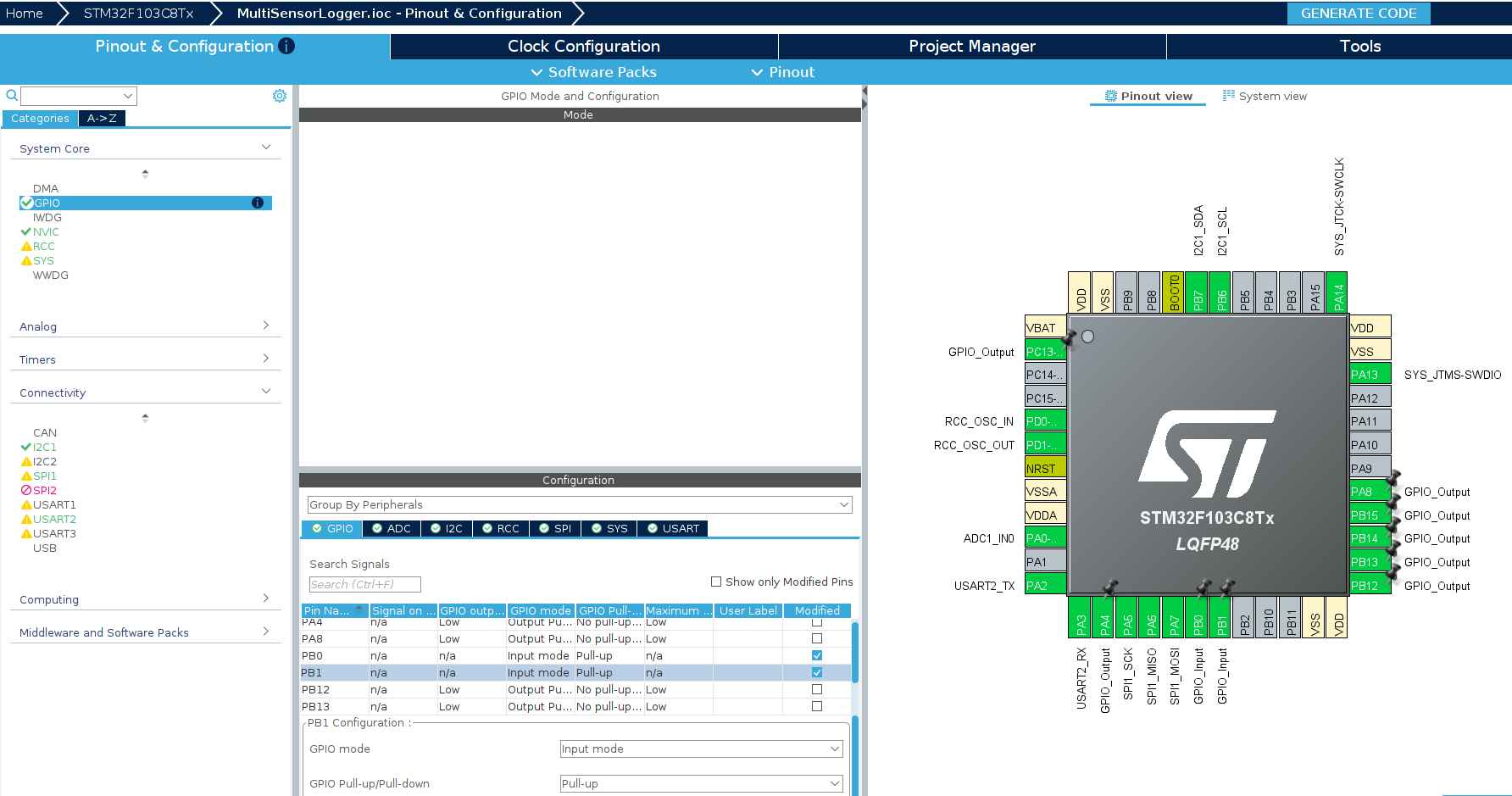
Project Manager: Click the Project Manager tab. Set Project Name to MultiSensorLogger, choose a project location, verify Toolchain / IDE is STM32CubeIDE. Click GENERATE CODE.
Import into CubeIDE: File > Import > General > Existing Projects into Workspace. Browse to the MultiSensorLogger folder. Build with Ctrl+B. You should see 0 errors, 0 warnings.
Your CubeMX configuration should match these after completing the steps above:
Generated Project Structure
After CubeMX generates and CubeIDE imports, you should see:
ディレクトリMultiSensorLogger/
ディレクトリCore/
ディレクトリInc/
main.h
stm32f1xx_hal_conf.h
stm32f1xx_it.h
ディレクトリSrc/
main.c
stm32f1xx_hal_msp.c
stm32f1xx_it.c
syscalls.c
sysmem.c
system_stm32f1xx.c
ディレクトリStartup/
startup_stm32f103c8tx.s
ディレクトリDrivers/
ディレクトリCMSIS/
…
ディレクトリSTM32F1xx_HAL_Driver/
…
MultiSensorLogger.ioc
STM32F103C8TX_FLASH.ld
This is the base CubeMX output. As we add the capstone code, we will create additional files inside Core/Inc/ and Core/Src/.
Peripheral Initialization Order
The initialization order matters for reliable startup:
if (sys.current.temperature<sys.temp_min) sys.temp_min=sys.current.temperature;
if (sys.current.temperature>sys.temp_max) sys.temp_max=sys.current.temperature;
if (sys.current.humidity<sys.hum_min) sys.hum_min=sys.current.humidity;
if (sys.current.humidity>sys.hum_max) sys.hum_max=sys.current.humidity;
/* Check alarm */
sys.current.alarm_active=sys.alarm_triggered;
Alarm_Check(&sys);
}
/* Display update every 500 ms */
if (now - tick_display >=500) {
tick_display = now;
Display_Update(&hi2c1, &sys);
}
/* SD card write every 1 second */
if (now - tick_sd >=1000) {
tick_sd = now;
if (sys.sd_card_ok) {
if (SD_Logger_Write(&sys.current)) {
sys.log_count++;
} else {
sys.sd_card_ok=SD_Logger_Check();
}
} else {
sys.sd_card_ok=SD_Logger_Check();
}
}
/* Bluetooth send every 2 seconds */
if (now - tick_bt >=2000) {
tick_bt = now;
if (BT_SendJSON(&huart2, &sys.current)!=1) {
sys.bt_connected=0;
} else {
sys.bt_connected=1;
}
}
/* Uptime counter */
if (now - tick_second >=1000) {
tick_second = now;
sys.uptime_seconds++;
}
HAL_Delay(10);
}
}
Project File Structure
ディレクトリMultiSensorLogger/
ディレクトリCore/
ディレクトリInc/
main.h
data_types.h
ssd1306.h
stm32f1xx_hal_conf.h
stm32f1xx_it.h
ディレクトリSrc/
main.c
bme280.c
ssd1306.c
sd_logger.c
bluetooth.c
display.c
alarm.c
font5x7.c
system_stm32f1xx.c
stm32f1xx_it.c
stm32f1xx_hal_msp.c
ディレクトリFATFS/
ディレクトリApp/
fatfs.c
ディレクトリTarget/
user_diskio.c
ディレクトリDrivers/
ディレクトリCMSIS/
…
ディレクトリSTM32F1xx_HAL_Driver/
…
MultiSensorLogger.ioc
Testing
Flashing the Firmware
In CubeIDE, click the Run button (green play icon) or use Run > Run As > STM32 C/C++ Application. If CubeIDE’s built-in GDB server fails (common on Ubuntu 20.04 or older due to GLIBC version requirements), flash from the command line instead:
The --reset flag resets the MCU after flashing so it starts running immediately. Without it, you need to press the NRST button on the Blue Pill.
Test Sequence
Check the onboard LED. After flashing, the LED should blink at roughly 1 Hz (500 ms on, 500 ms off). This confirms the firmware is running and the main loop is executing.
Check the OLED. It should briefly show “MULTI-SENSOR DATA LOGGER INITIALIZING…” then switch to the live data page showing temperature, threshold, pot value, uptime, and alarm status. If the display is blank, check I2C wiring (PB6 = SCL, PB7 = SDA) and verify VCC is connected to 3.3V.
Verify the potentiometer. Turn the knob. The THR value on the OLED should change between 15.0 and 50.0 degrees C. The POT value shows the raw ADC reading (0 to 4095). Any potentiometer value from 1K to 100K works. If no potentiometer is connected, the value will float randomly.
Trigger the alarm. Turn the potentiometer so THR drops below the current temperature reading (T). The OLED should switch from “ARMED - OK” to ”** ALARM **”. If LEDs and a buzzer are connected, the red LED (PA8) lights up, the relay (PB12) activates, and the buzzer (PB13) sounds.
Test button functions (if connected). Button 1 (PB0 to GND) cycles display pages. Button 2 (PB1 to GND) arms and disarms the alarm. Buttons use internal pull-ups, so each button connects between the pin and GND with no external resistor.
Add the BME280 sensor. Connect to the same I2C bus as the OLED (PB6 SCL, PB7 SDA, 3.3V, GND). Both devices share the bus at different addresses (OLED = 0x3C, BME280 = 0x76).
Test the SD card. After adding SD card logging code, remove the card, insert it into a computer, and check for datalog.csv with timestamped sensor readings.
Pair the HC-05 Bluetooth module. Open a serial terminal on your phone or computer. JSON lines should arrive every 2 seconds.
Power Considerations
Peripheral
Active Current
Notes
STM32F103 (72 MHz)
~30 mA
Dominant consumer
BME280
~0.3 mA
Very low; 1 uA in sleep
SSD1306 OLED
~10 mA
Depends on pixels lit
SD card (write)
~50 mA peak
Significant spikes during write
HC-05
~30 mA
~8 mA in connected idle
Relay module
~70 mA
Coil current when active
Total (worst case)
~190 mA
Exceeds USB 100 mA; use external supply
For battery operation, consider powering down peripherals when idle. The BME280 can be put into sleep mode between readings. The OLED can be turned off with command 0xAE. The HC-05 can enter low-power mode via AT commands. The STM32 itself supports Stop mode with wake-on-interrupt from a timer, consuming under 20 uA.
Production Notes
From Breadboard to Product
PCB layout: Place decoupling capacitors (100 nF ceramic) within 5 mm of every IC power pin. Route I2C traces as short differential pairs. Keep the SD card traces short and away from noisy PWM signals. Use a ground pour on the bottom layer.
Power budgeting: The total system draws up to 190 mA under worst case. A USB power source provides 500 mA, which is sufficient. For battery operation with a LiPo cell, add a 3.3V LDO regulator rated for 300 mA or more. Budget for the relay coil current, which dominates during alarm state.
Enclosure design: The OLED and buttons need panel cutouts. The BME280 should be exposed to ambient air (not sealed inside). Route the SD card slot to be accessible. Include ventilation holes near the sensor to avoid heat buildup from the voltage regulator affecting temperature readings.
Field testing: Deploy the logger for 24 hours and verify the SD card data covers the full period without gaps. Check that the watchdog never triggers (which would appear as a gap in timestamps). Monitor Bluetooth range: the HC-05 typically reaches 10 meters indoors.
Reliability: Add a startup self-test that checks each peripheral (BME280 chip ID, OLED ACK, SD card mount, UART echo) and reports failures on the OLED before entering the main loop. In production firmware, store a failure log in the STM32’s backup registers so you can diagnose field failures.
Course Summary
This course covered ten lessons progressing from basic GPIO interfacing to a complete multi-sensor integrated system:
Lesson
Topic
Key Skills
1
GPIO and Digital Interfacing
CubeIDE setup, HAL GPIO, interrupts, relay and ultrasonic control
2
ADC and Analog Signal Conditioning
12-bit ADC, signal conditioning, voltage dividers, op-amp buffers
3
PWM, Timers, and Motor Control
Timer PWM generation, servo control, DC motor H-bridge, input capture
4
I2C: Sensors and Displays
I2C protocol, BME280, SSD1306 OLED, EEPROM, bus scanning
DMA architecture, NVIC priorities, bxCAN, two-node CAN network
10
Capstone: Multi-Sensor Data Logger
Bus sharing, timing architecture, state machine UI, system integration
Where to Go Next
IoT Systems
The IoT Systems course takes these sensor nodes online. Connect your STM32 or ESP32 to MQTT brokers, build cloud dashboards, and implement over-the-air firmware updates. The data logger you built here becomes the edge device in a full IoT architecture.
Edge AI / TinyML
The Edge AI and TinyML course adds machine learning inference directly on microcontrollers. Run anomaly detection on sensor data, classify audio with neural networks, and deploy TensorFlow Lite models on Cortex-M devices. The sensor interfacing skills from this course provide the data acquisition foundation that every TinyML application needs.

Comments