Four-Bar Linkage
Where it is used: robotic arms, windshield wipers, suspensions, grippers
Analysed in: Lessons 1, 2, 3, 4, 6 (mobility, position, velocity, acceleration, force)
このコンテンツはまだ日本語訳がありません。
Planar mechanics is the study of how machines move and transmit force in a two-dimensional plane. It is the analytical foundation behind robotic arms, engines, lift platforms, clamps, and most of the linkages inside everyday machines.
This course teaches that analysis through four mechanisms you return to in every lesson: the four-bar linkage, the slider-crank, the scissor lift, and the toggle clamp. Rather than meeting a new example each week, you study these four in depth, viewing each through a different question: first whether it moves, then where each link is positioned, how fast the links move, how hard they accelerate, and what forces that motion demands. Every result you work out by hand can be checked in an interactive simulator.
Each lesson applies one analytical lens to the same mechanisms. The questions build on each other.
| Lesson | The one question it answers | The skill you gain |
|---|---|---|
| 1. Kinematic Joints and Constraint Analysis | Will it move, and how many motors does it need? | Count degrees of freedom, classify joints, recognise over-constraint |
| 2. Position Analysis of Planar Linkages | Where is every link? | Construct positions to scale, then solve the vector loop for any configuration |
| 3. Velocity Analysis and Instantaneous Centers | How fast is each part moving? | Draw velocity polygons, then confirm the velocities by differentiating the loop |
| 4. Acceleration Analysis and Dynamic Forces | How fast is the motion changing, and what force does that take? | Draw acceleration polygons and find the inertia forces they create |
| 5. Cam-Follower Systems and Motion Programming | How do I design a shape that produces a chosen motion? | Program follower motion and generate cam profiles |
| 6. Force Analysis and Mechanism Synthesis | What forces flow through the mechanism, and how do I design for them? | Size actuators and links, then synthesise new mechanisms |
Lessons 2 to 4 share a single thread. You write a mechanism’s vector loop equation once in Lesson 2, differentiate it once for velocity in Lesson 3, and differentiate it again for acceleration in Lesson 4. Lesson 6 then turns to the forces that motion requires, and to the reverse problem of designing a mechanism to meet a specification. Lesson 5 covers the one case where you design the motion directly: the cam profile.
Because the mechanisms stay the same, concepts are introduced once and reused. Lesson 1 defines the mechanisms and their joints; later lessons refer back to them instead of starting over.
You analyse these four mechanisms from a new angle in each lesson. Each has an interactive simulator for checking your work.
Four-Bar Linkage
Where it is used: robotic arms, windshield wipers, suspensions, grippers
Analysed in: Lessons 1, 2, 3, 4, 6 (mobility, position, velocity, acceleration, force)
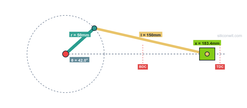
Slider-Crank
Where it is used: engines, pumps, compressors, presses
Analysed in: Lessons 1, 2, 3, 4, 6 (the classic rotation-to-translation converter)
Scissor Lift
Where it is used: work platforms, lift tables, dock levellers
Analysed in: Lessons 1, 2, 3, 4, 6 (height, motion, actuator force, stability)
Toggle Clamp
Where it is used: machining fixtures, riveters, crushers
Analysed in: Lessons 1, 3, 6 (self-locking, force amplification, stress sizing)
Lesson 5 adds the cam-follower, the higher-pair mechanism used in valve trains, indexing tables, and automated machinery, where the goal is to design a surface that produces an exact, programmed motion.
Every calculation in this course can be verified in the browser. Each mechanism has an interactive simulator, paired with a set of guided Python experiments in the Mechanism Design and Simulation course.
Four-Bar Linkage Simulator
Open simulator Experiments: Four-Bar Linkage Experiments
Crank-Slider Simulator
Open simulator Experiments: Crank-Slider Experiments
Scissor Lift Simulator
Open simulator Experiments: Scissor Lift Experiments
Toggle Clamp Simulator
Open simulator Experiments: Toggle Clamp Experiments
Real-world system problem A working machine that depends on the lesson’s analysis, with the specific question it raises.
Fundamental theory The mathematics and kinematics you need, derived from first principles.
Worked applications, drawn first Each problem is solved graphically before it is solved with equations: you draw the space diagram to scale, then the velocity diagram, then the acceleration diagram, and measure the answers off the page. The closed-form calculation and the simulator then confirm what you drew.
Design guidelines Practical rules for using the analysis in your own designs.
The four mechanisms here (the four-bar, slider-crank, scissor lift, and toggle clamp, plus the cam of Lesson 5) are the same ones you build parametrically in the Parametric Mechanical CAD with FreeCAD course. The kinematics you learn here (loop closure, extreme positions, velocity and acceleration) is exactly what sets the dimensions and constraints of those CAD models, so the two courses reinforce each other: analyse the motion here, then draw and dimension the mechanism there.
Vector mechanics, basic calculus, and elementary physics. The graphical work needs only a drawing set; the analysis scripts use Python with NumPy and Matplotlib, so a working knowledge of Python is helpful but not required to follow the worked solutions.
Start with Lesson 1: Kinematic Joints and Constraint Analysis to learn whether a mechanism moves before you analyse how it moves.