Programmed motion
A cam stores an arbitrary motion law, including dwells, that no simple linkage can reproduce.
Every mechanism so far was a linkage you were handed and then analysed. The cam inverts the problem: you decide the exact motion the follower must make, its rise, its dwell, its return, and then you design the curved surface that delivers it. The danger is in the curve. Choose a motion law whose acceleration jumps, and the follower receives an infinite jerk at that instant: a hammer blow that wears the contact, makes noise, and shakes the machine at high speed. The whole craft of cam design is shaping the motion so that nothing jumps. In this lesson you program the motion with SVAJ diagrams, lay out the cam profile by hand, and size the base circle from the pressure angle. #CamDesign #MotionProgramming #Cycloidal
By the end of this lesson, you will be able to:
An engine valve must snap open, stay fully open while gas flows, then close, all in a fixed fraction of a crank revolution, and repeat without fail millions of times. A packaging machine must advance a film, pause precisely while a print head fires, then advance again. These are dwell motions: the output must hold still for part of the cycle and move on a programmed schedule for the rest. A linkage cannot dwell cleanly, but a cam can: its profile is a stored motion program that the follower reads off as the cam turns.
The cam-follower contact is the higher pair from the joint classification: line contact that both rolls and slides, removing only one degree of freedom. That single contact is where all the force passes, so the shape of the cam decides both the motion and whether the follower is driven smoothly or hammered.

Engineering Question: Given the motion the follower must make (its rises, dwells, and returns), what surface produces it, and is that motion smooth enough to run at speed?
Programmed motion
A cam stores an arbitrary motion law, including dwells, that no simple linkage can reproduce.
Smoothness sets the speed limit
An acceleration jump is an infinite jerk: impact, noise, and wear. The motion law caps how fast a cam can run.
Force transmission
The pressure angle decides how much of the contact force does useful work. Too large and the follower jams.
A higher pair
The single rolling-sliding contact carries all the load, so its geometry and the base-circle size govern stress and life.
S, V, A, J
A cam motion is described by four diagrams against cam angle
The fundamental law of cam design: for a cam to run at speed, the displacement and its first two derivatives (
Four Motion Laws for a Rise of Height h over Angle β
Every peak below has the same shape: a pure number times
| Motion law | Acceleration at the ends | Suitability | ||
|---|---|---|---|---|
| Uniform (constant velocity) | infinite velocity jump | only with rounded ends | ||
| Parabolic (constant accel) | jumps (finite, but step) | low speed | ||
| Simple harmonic (SHM) | jumps from zero at a dwell | moderate speed | ||
| Cycloidal | zero at both ends | high speed, smoothest |
Cycloidal motion has the highest peak acceleration of the four, yet it is the best for high speed because its acceleration starts and ends at zero, so it joins a dwell with no jump and no infinite jerk. Simple harmonic motion looks smooth but its acceleration is a cosine that is at full value at the ends, so where a rise meets a dwell the acceleration steps from a maximum to zero, an infinite jerk.
Pressure Angle
For a radial translating follower (no offset), the pressure angle
where
For a roller follower, replace
Where the maximum falls. The numerator
This runs about half a degree below the true peak, so treat it as a slight under-estimate and keep a little margin against the
This is the central worked example. We program a rise and draw its displacement, velocity, and acceleration to scale, the graphical heart of cam design. It follows the same draw, solve, simulate rhythm as the linkage lessons: draw the motion to scale, find its peaks analytically, then confirm in the simulator.
Simulator and hands-on lab
Hands-on lab: Continue in the Cam and Follower Experiments lab (siwit.co/CFM), which plots this SVAJ chain and compares the motion laws. Build the cam as a part in the Cam and Follower Mechanism CAD lesson; for pure simple-harmonic follower motion, see the Scotch-Yoke Mechanism.
Plot the three curves to scale against cam angle. Choose a vertical scale for each (for example 1 cm = 5 mm of lift for
Displacement of the cycloidal rise:
Velocity and acceleration (per unit cam angle):
Read the diagram. Plotted against

Convert the rise angle to radians first.
Write down the factors for the cycloidal law:
Peak velocity per unit cam angle, at mid-rise (
Peak acceleration per unit cam angle, at the quarter points:
Convert to real units at the cam speed
Sanity-check the size of the answer.
Compare with simple harmonic motion. SHM over the same rise peaks at
Open the simulator (siwit.co/CFM), set a cycloidal rise of
Read the peaks. Velocity peaks at about
Break the law. Switch the rise to simple harmonic: the peak acceleration drops to about
With the motion programmed, the cam profile is laid out graphically by inversion: imagine the cam fixed and the follower walking around it. At each cam angle the follower sits a distance
Build it and explore
The Cam and Follower Simulator draws this pitch curve and cam profile live as you set the program, so you can check your hand layout against it. Then reproduce the profile in CAD with the Cam and Follower Mechanism lesson, which generates the same profile from the same motion program.
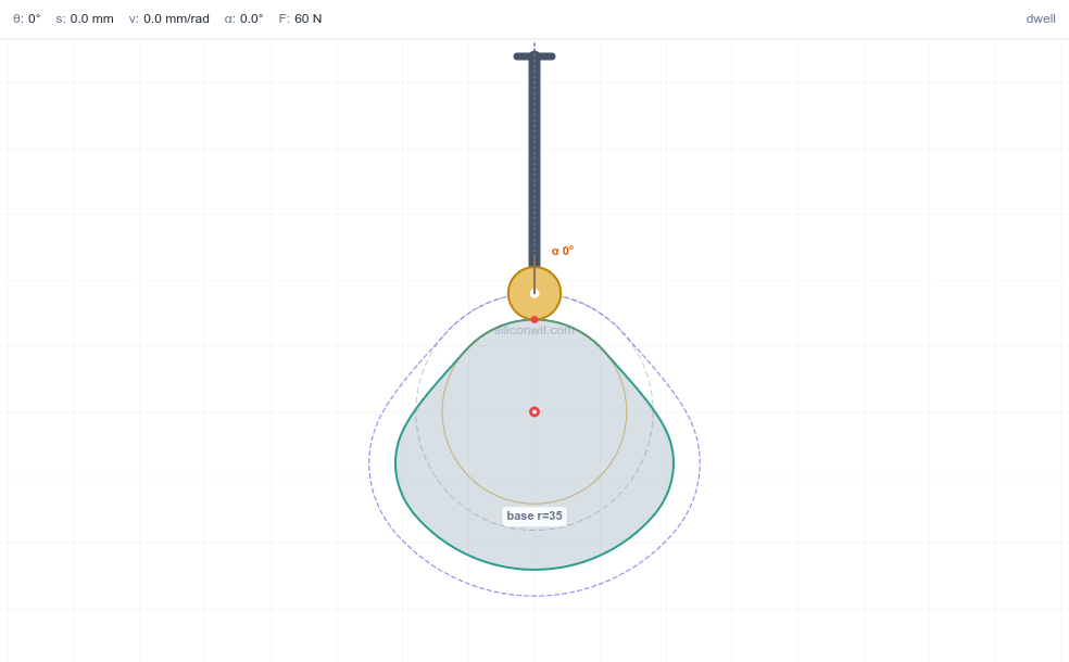
Draw the base circle of radius
Divide the cam angle into convenient steps (every
Step off the displacement. At each angle, read
Join the points with a smooth curve. This is the pitch curve, the path of the follower centre. For a roller follower, the actual cam surface is offset inward from the pitch curve by the roller radius. ✅

Pitch radius. The profile radius at any angle is
The dwells are circular arcs. Where the follower holds still, the profile is a constant-radius arc (concentric with the base circle). The rise and fall are the shaped transitions between them. ✅
Roller offset. Drawing the pitch curve first and offsetting by the roller radius is the standard route, and it is exactly what the CAD model does when you sweep the roller around the program. ✅
The base circle is not free: too small and the pressure angle grows until the follower jams. This is where the cam’s size is actually decided.
Check the first guess by hand. Use the mid-rise form
A full numerical sweep of the rise gives
Size the base circle directly rather than guessing again. Rearranging for
Because the hand form under-estimates by about a degree, round up rather than taking
Confirm the chosen size. At
Read the trade-off from the plot below: the larger base circle lowers the whole pressure-angle curve under the

Open the simulator (siwit.co/CFM) with the cycloidal rise and a knife-edge follower, set the base radius to
Enlarge the base circle. Raise the base radius to
Program first, shape second
Choose the motion law and draw the SVAJ diagrams before laying out any profile. The law sets the dynamics.
No acceleration jumps
Keep displacement, velocity, and acceleration continuous across the dwells. Cycloidal motion does this; uniform and plain parabolic do not.
Size from the pressure angle
Pick the base circle so the peak pressure angle stays within the guide (about
Pitch curve then roller offset
Lay out the pitch curve from the program, then offset by the roller radius for the cutting profile.
| Quantity | Relation |
|---|---|
| Cycloidal displacement | |
| Motion-law factors | |
| Factors: cycloidal / SHM / parabolic | |
| Peaks at cam speed | |
| Pressure angle | |
| Max pressure angle (cycloidal) | |
| Base circle for a given | |
| Pitch-curve radius |
The SVAJ diagrams, cam profile, and pressure-angle curves here were drawn from the motion equations and reproduced with a few lines of Python (NumPy). To do all of it interactively, the Cam and Follower Mechanism Simulator plots the live SVAJ chain, flags any motion law that violates the fundamental law, sizes the base circle against the pressure angle, and checks the radius of curvature for undercutting, the same analysis this lesson does by hand. The Cam and Follower Experiments turn it into structured, Python-verified exercises. To turn the profile into a part, build it in the Cam and Follower Mechanism CAD lesson, which sweeps the same program into a solid cam.
Next, Force Analysis and Mechanism Synthesis returns to the linkages and closes the course: free-body diagrams and force polygons give the joint reactions, the transmission angle measures force quality, and synthesis runs the whole process backward to design a mechanism that meets a force and motion specification.
Comments