Master combined bending and torsion analysis through practical applications in drone arms, wind turbine shafts, and robotic grippers, covering von Mises failure theory, principal stress transformation, and safety factor design for multi-axis loading conditions. #VonMisesStress #CombinedLoading #FailureTheory
Learning Objectives
By the end of this lesson, you will be able to:
Analyze simultaneous bending and torsional stresses in shaft components
Calculate equivalent stresses using von Mises and maximum shear stress theories
Apply combined loading analysis to robotic wrist joint design
Predict failure modes under multi-axis loading conditions
Engineering Challenge: Combined Loading in Mechanical Systems
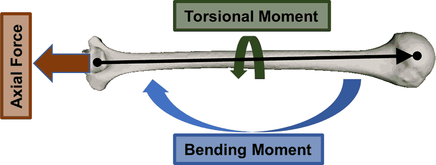
Combined loading is a critical design consideration across diverse engineering applications, from robotic manipulators handling multi-axis forces, to wind turbine shafts transmitting power while supporting blade weight, to drone arms balancing thrust loads with motor torque. Understanding combined stress analysis enables engineers to predict failure modes under complex loading, assess equivalent stresses against material limits, and optimize structural designs for reliability under simultaneous bending, torsion, and axial forces.
The Universal Combined Loading Challenge
Across mechanical, aerospace, and robotics engineering, structural members must resist multiple simultaneous loads to maintain:
Engineering Question: How do we analyze shafts and structural members experiencing simultaneous bending moments, torsional loads, and axial forces, assess them against material strength limits using equivalent stress theories, and design safe solutions that meet performance requirements?
Why Combined Loading Analysis Matters
Consequences of Inadequate Combined Stress Analysis:
Unexpected failures: Structural collapse from underestimating equivalent stress
Safety hazards: Catastrophic failure in wind turbines, aircraft, or robotic systems
Shortened service life: Premature fatigue failure under cyclic multi-axis loading
Performance degradation: Excessive deflection compromising precision and functionality
Material waste: Over-design from conservative assumptions without proper analysis
Benefits of Proper Combined Loading Analysis:
Predictable performance within established safety margins using validated failure theories
Optimized material usage through accurate equivalent stress calculations
Informed design trade-offs between weight, strength, and reliability
Application-specific safety factors tailored to loading conditions (not arbitrary rules)
Reliable fatigue life prediction for cyclic combined loading scenarios
Fundamental Theory: Combined Stress Analysis
The Principle of Stress Superposition
When multiple loads act simultaneously on a structural member, the principle of superposition allows us to calculate the total stress state by combining individual stress components algebraically.
📋 Why Superposition Works
Foundation: Superposition is valid when:
Material behaves linearly (stress proportional to strain within elastic range)
Deformations are small (geometry doesn’t significantly change under load)
Loads are independent (one load doesn’t affect how another is applied)
Practical Implication: Calculate stresses from each load type separately, then combine them to get total stress state.
Stress Components in Combined Loading
📊 Combined Normal Stress
Individual stress components:
From axial loading:
Where = axial force, = cross-sectional area
From bending moment:
Where = bending moment, = distance from neutral axis, = second moment of area
Combined normal stress (at any point):
Sign convention:
Tension: positive (+)
Compression: negative (−)
Use + on tension side of beam, − on compression side
Critical insight: Maximum normal stress occurs at the outer fiber farthest from the neutral axis.
🌀 Combined Shear Stress
Individual shear stress components:
From torsion:
Where = torque, = radial distance, = polar moment of inertia
From transverse shear force:
Where = shear force, = first moment of area, = width
Combined shear stress:
For most shaft problems: Torsional shear dominates, and transverse shear is negligible.
Critical insight: Maximum shear stress from torsion occurs at the outer surface of circular shafts.
Principal Stress Transformation
When normal and shear stresses act together, the actual maximum stress occurs on different planes than the original coordinate system.
🔱 Principal Stress Formulas
For 2D stress state (σₓ, σᵧ, τₓᵧ):
Where:
= Maximum principal stress (largest normal stress on any plane)
= Minimum principal stress (smallest normal stress on any plane)
Principal planes have zero shear stress
For combined bending + torsion (common case: σᵧ = 0):
Physical meaning: These are the “true” maximum and minimum stresses at the point, accounting for stress direction.
🌀 Maximum Shear Stress
In-plane maximum shear stress:
Absolute maximum shear stress (considering all 3D principal stresses):
Where = third principal stress (often zero for surface stresses)
Critical insight: Maximum shear occurs on planes oriented 45° from principal stress directions.
Failure Theories for Combined Loading
Different materials fail through different mechanisms. We use failure theories to predict when combined stresses will cause yielding or fracture.
❌ NOT for ductile materials under combined loading
Why limited: Ignores beneficial effects of compressive stresses and doesn’t account for shear-induced yielding.
Comparison of Failure Theories
📊 Which Theory to Use?
Criterion
Von Mises
Tresca
Max Normal Stress
Best for
Ductile metals (steel, Al)
Quick conservative check
Brittle materials
Accuracy
Most accurate
~15% conservative
Poor for ductile
Complexity
Moderate
Simple
Very simple
Industry use
✅ Standard
✅ Common backup
⚠️ Limited
Safety factor
Typical: 1.5–3.0
Can use lower SF
Higher SF needed
Design recommendation:
Primary analysis: Use von Mises for ductile materials (99% of mechanical design)
Verification: Check with Tresca as conservative backup
Brittle materials: Use Maximum Normal Stress for ceramics, cast iron, concrete
Practical Design Guidelines
🎯 Critical Stress Locations
For circular shafts under bending + torsion:
Check outer surface (maximum r)
On tension side of bending
Combined σ and τ are both maximum there
⚖️ Typical Safety Factors
Static loading:
Well-known loads: SF = 1.5–2.0
Uncertain loads: SF = 2.0–3.0
Dynamic/fatigue loading:
SF = 3.0–6.0 (higher for critical)
🔄 Simplified Formula
For shaft design (bending + torsion):
Quick diameter sizing!
Application 1: Drone Arm Design (Mechatronics)
A lightweight quadcopter drone uses hollow carbon fiber arms to support the motor and propeller assemblies. Each arm must withstand both vertical thrust forces from the rotor and torsional moments from motor operation during flight.
Enter the combined surface stress (the bending sigma and the torsional tau) into the Mohr’s circle simulator and read the principal stresses and the safety factor:
Safety factor target: 3.0–5.0 (typical for drone applications with dynamic loads)
Operating conditions: Flight loads with vibration and impact
Step 1: Calculate Section Properties
Click to reveal section property calculations
For a hollow circular tube with outer diameter D and inner diameter d:
Cross-sectional area:
Second moment of area (for bending stress):
Polar moment of inertia (for torsional stress):
Critical dimensions:
Outer radius: mm (where stresses are maximum)
Distance from neutral axis to outer fiber: mm
Design insight: The hollow tube maximizes bending and torsional stiffness while minimizing weight—critical for drone performance.
Step 2: Calculate Internal Forces and Individual Stresses
Click to reveal stress component calculations
Calculate bending moment at fixed end (from cantilever beam analysis):
For a cantilever with point load F at the free end:
Bending stress at outer fiber (maximum tension/compression):
Using flexure formula :
Location: Occurs at top and bottom of tube (tension on one side, compression on other)
Torsional shear stress at outer surface:
Using torsion formula :
Location: Maximum at outer surface, acts circumferentially
Identify critical stress location:
The outer surface on the tension side of bending experiences:
Maximum normal stress: MPa (tension)
Maximum shear stress: MPa (torsion)
These combine to create the highest equivalent stress.
Physical interpretation: The arm bends downward under rotor thrust (creating tension on top surface) while simultaneously twisting about its axis from motor torque.
Step 3: Apply Von Mises Failure Theory
Click to reveal von Mises equivalent stress calculation
Stress state at critical point (outer surface, tension side):
Normal stress: MPa
Shear stress: MPa
Other components: , (thin-walled assumption)
Von Mises equivalent stress formula (for combined bending + torsion):
Substituting values:
Physical meaning:
The combined effect of bending and torsion produces an equivalent uniaxial stress of 33.0 MPa. This is the “effective” stress that the material experiences.
Why von Mises? Carbon fiber composites in the fiber direction behave similarly to ductile materials, making von Mises theory appropriate for this analysis.
Step 4: Safety Factor Assessment and Design Evaluation
Click to reveal safety factor analysis
Calculate safety factor:
Design assessment:
Criterion
Value
Status
Von Mises stress
33.0 MPa
✅
Material yield
400 MPa
✅
Safety factor
12.1
✅ Excellent
Typical drone SF target
3.0–5.0
✅ Exceeded
Design margin analysis:
Stress utilization: of material capacity
Available margin: Nearly 12× the actual stress
Conclusion: Design is highly conservative (very safe but possibly overdesigned)
Stress contribution analysis:
From the von Mises stress formula , we can determine each component’s contribution:
Bending contribution:
Torsion contribution:
For our drone arm:
Bending contributes: of von Mises stress
Torsion contributes: of von Mises stress
Key insight: Bending dominates — motor torque has minimal structural impact
Design recommendations:
✅ Current design is safe with excellent margins (SF = 12.1 >> 3.0 target)
Could reduce wall thickness to t = 1.5 mm (stress increases ~33%, still SF > 8)
Could use smaller diameter (D = 18 mm) for weight savings
Current design provides excellent margin for dynamic loads, vibration, and fatigue
When to keep current conservative design:
Crash resistance is critical (landing impacts, collisions)
Vibration and dynamic loads significant (rotor imbalance, wind gusts)
Fatigue life important (SF > 10 excellent for high-cycle loading from rotor operation)
Application 2: Wind Turbine Main Shaft (Mechanical)
The main shaft of a horizontal-axis wind turbine transmits power from the rotor to the gearbox while supporting the rotor weight and wind loads. This shaft experiences combined bending from distributed loads and torsion from power transmission.
🔧 Equivalent System Model
Geometric Configuration:
Hollow steel shaft: Outer Diameter (OD) = 100 mm, Inner Diameter (ID) = 80 mm
Wall thickness: t = 10 mm
Total shaft length: L = 2.0 m (2000 mm) from bearing A to point P1
Span between bearings: AB = 1.5 m (1500 mm) from bearing A (pinned) to bearing B (roller)
Overhang length: BP1 = 0.5 m (500 mm) from bearing B to rotor at P1
Critical section: At support B where maximum negative bending moment occurs
Loading Conditions:
Point load P1 = 1200 N at tip of overhang (x = L = 2.0 m) - rotor assembly weight (hub + blades)
Distributed load W = 300 N/m along entire shaft (0 ≤ x ≤ L = 2.0 m) - shaft self-weight
Total distributed load: W_total = W × L = 300 × 2.0 = 600 N
Transmitted torque T = 5000 N·m constant along entire shaft (from rotor power transmission)
Support reactions: R_A (to be calculated), R_B (to be calculated)
Cross-Section Properties:
Second moment of area: I = π(D⁴ - d⁴)/64 = 2.896 × 10⁶ mm⁴
Polar moment of inertia: J = π(D⁴ - d⁴)/32 = 5.792 × 10⁶ mm⁴
Distance to extreme fiber: c = 50 mm
Material & Safety:
Material: AISI 1045 steel (σ_yield = 310 MPa)
Safety factor target: 2.5–4.0 (typical for power transmission with fatigue loading)
Operating conditions: Rotating shaft, cyclic wind loads, 20+ year service life
Step 1: Calculate Support Reactions and Determine Critical Section
Click to reveal support reactions and critical section analysis
For an overhang beam with point load P1 at the tip and uniformly distributed load W along the entire shaft, we must first find support reactions, then determine where maximum bending moment occurs.
Given loads:
Point load: N at tip (x = L = 2.0 m)
Distributed load: N/m along entire shaft (0 ≤ x ≤ L = 2.0 m)
Total distributed load: N
Total shaft length: m
Span between bearings: m
Overhang length: m
Calculate support reaction at B using moment equilibrium about A:
Taking moments about support A (counterclockwise positive):
Calculate reaction at A from vertical equilibrium:
Result: N ↓ (downward reaction - overhang lifts the beam at A!)
Maximum bending moment location:
For overhang beams with load on overhang, the critical section is at support B where the maximum negative moment occurs (tension on top fiber, compression on bottom).
Calculate maximum bending moment at support B:
Using the overhang section (from B to P1) for clarity:
The overhang has:
Point load at distance from B
Distributed load over length , with resultant at from B
Converting to N·mm: N·mm (magnitude used for stress calculations)
Torsional moment:
Torque is constant along entire shaft:
Critical section identified:At support B (bearing closest to rotor) where maximum negative bending moment of 637.5 N·m occurs. The overhang configuration is more realistic for wind turbines where the rotor hub extends beyond the forward bearing.
Physical insight: The combined effect of rotor weight (P1 = 1200 N at distance L from A) and shaft self-weight (W = 300 N/m along entire length L) creates a significant negative moment at bearing B. The overhang portion (BP1 = 0.5 m) causes tension on the top fiber at B. The downward reaction at bearing A (200 N ↓) shows how the overhang lifts the rear of the shaft.
Step 2: Calculate Section Properties
Click to reveal section property calculations
For a hollow circular shaft with outer diameter D and inner diameter d:
Cross-sectional area:
Second moment of area (for bending stress):
Polar moment of inertia (for torsional stress):
Critical dimensions:
Outer radius: mm (where stresses are maximum)
Distance from neutral axis to outer fiber: mm
Design note: The 10 mm wall thickness provides good balance between strength and weight for power transmission applications.
Step 3: Calculate Individual Stress Components
Click to reveal stress calculations at critical section
At the critical section (support B, outer surface):
Bending stress at outer fiber:
Using flexure formula with moment magnitude N·mm:
Location: Maximum at top and bottom of shaft. At support B with negative moment, tension occurs on top fiber (opposite of typical simply-supported beam)
Torsional shear stress at outer surface:
Using torsion formula :
Location: Maximum at outer surface, uniform around circumference
Identify critical stress state:
The outer surface on the tension side (top fiber at support B) experiences:
Normal stress: MPa (tension)
Shear stress: MPa (torsion)
Stress comparison:
Notice that torsional stress still dominates over bending stress:
MPa (much larger)
MPa (moderate, but still significantly smaller than torsion)
This is typical for power transmission shafts where torque is the primary design consideration. However, the overhang configuration creates higher bending moment (637.5 N·m) than a simply-supported beam would (400 N·m), making the combined loading (P1 + W) effect more pronounced.
Physical interpretation: The shaft is primarily loaded in torsion (power transmission), with significant bending from the combined rotor assembly weight (P1) and shaft self-weight (W) on the overhang. The overhang configuration creates higher bending moment than a simply-supported beam, making the rotor weight placement critical.
Step 4: Apply Von Mises Failure Theory
Click to reveal von Mises equivalent stress calculation
Stress state at critical point (outer surface, top fiber at support B):
Normal stress: MPa (tension on top due to negative moment)
Shear stress: MPa
Other components: ,
Von Mises equivalent stress formula (for combined bending + torsion):
Substituting values:
Physical meaning:
The combined loading results in an equivalent uniaxial (von Mises) stress of 75.6 MPa. While the stress state remains dominated by torsion (43.2 MPa), the overhang loading introduces an additional bending moment at the support, increasing the bending stress to 11.0 MPa compared with what would be obtained under a simply supported idealization. As a result, the realistic loading case (P1 + W) produces a higher equivalent stress than simplified models.
Key insight: When , the von Mises stress is approximately , confirming torsion dominates.
Step 5: Safety Factor Assessment and Design Evaluation
Click to reveal safety factor analysis
Calculate safety factor:
Design assessment:
Criterion
Value
Status
Von Mises stress
75.6 MPa
✅
Material yield
310 MPa
✅
Safety factor
4.10
✅ Excellent
Typical turbine SF target
2.5–4.0
✅ Met
Design margin analysis:
Stress utilization: of material capacity
Available margin: 4.10× the actual stress
Conclusion: Design has appropriate safety margin for rotating machinery
Design evaluation:
✅ Design is adequate with good safety margins
Why SF = 4.10 is appropriate:
Wind turbines experience fatigue loading (cyclic stress from rotation)
Dynamic loads from gusts and turbulence require margin
Longer service life (20+ years) needs conservative design
Consequence of failure is severe (turbine collapse, downtime)
Stress contribution breakdown:
Torsion contributes:
Bending contributes:
Overhang configuration insights:
✅ More realistic for wind turbines (rotor extends beyond forward bearing)
✅ Negative moment at B (637.5 N·m) creates tension on top fiber
✅ Higher bending moment than simply-supported configuration
✅ Downward reaction at A (200 N ↓) demonstrates overhang lifting effect
Design verification:
✅ Safety factor (4.10) adequate for fatigue and dynamic loads
✅ Torsion dominates (97.9%), but bending contribution (2.1%) is realistic
✅ Hollow section optimizes strength-to-weight ratio
A precision robotic gripper uses aluminum fingers to grasp and manipulate objects. Each finger must withstand bending forces from gripping pressure and torsional moments from surface friction when holding cylindrical parts.
🔧 Equivalent System Model
Geometric Configuration:
Rectangular cross-section: width b = 8 mm, height h = 12 mm
Finger length: L = 60 mm from palm (fixed support) to tip (free end)
Critical section: Fixed end where bending moment is maximum
Loading Conditions:
Grip force: F = 20 N perpendicular to finger at tip (causes bending)
Friction torque: T = 0.5 N·m = 500 N·mm about finger axis (from gripping cylindrical objects)
Bending moment at fixed end: M = FL = 20 × 60 = 1200 N·mm
Cross-Section Properties:
Area: A = bh = 96 mm²
Second moment of area (bending): I = bh³/12 = 1,152 mm⁴
Distance to extreme fiber: c = h/2 = 6 mm
Torsional constant (rectangular): K ≈ 2,710 mm⁴ (using β = 0.196 for aspect ratio h/b = 1.5)
Material & Safety:
Material: Aluminum 6061-T6 (σ_yield = 275 MPa)
Safety factor target: 3.0–5.0 (typical for robotic grippers with repeated loading)
Operating conditions: High-cycle fatigue from repeated gripping operations
Note: Rectangular sections use different torsion formulas than circular shafts!
Step 1: Calculate Rectangular Section Properties
Click to reveal section property calculations
For a rectangular cross-section (width b, height h), formulas differ from circular sections:
Cross-sectional area:
Second moment of area (bending about horizontal neutral axis):
For bending about the axis parallel to width b:
Distance to extreme fiber:
Torsional constant for rectangular sections:
For rectangles, torsional resistance is NOT given by polar moment J. Instead:
For aspect ratio :
Using torsional constant formula for rectangles:
Where depends on aspect ratio. For , (from tables)
Maximum torsional shear stress location:
For rectangular sections, maximum shear stress occurs at the midpoint of the longer side (h = 12 mm).
Key difference: Rectangular sections are less efficient at resisting torsion than circular sections of similar area.
Step 2: Calculate Bending Moment and Bending Stress
Click to reveal bending stress calculations
Calculate bending moment at fixed end (cantilever with tip load):
For a cantilever beam with point load F at free end:
Bending stress at extreme fiber:
Using flexure formula :
Location: Maximum at top and bottom surfaces at the fixed end (tension on one side, compression on other)
Critical location for bending:
The outer fiber (top or bottom surface) at the fixed end experiences maximum bending stress.
Physical interpretation: The finger bends like a diving board when the grip force is applied at the tip.
Click to reveal torsional stress calculations for rectangular section
Important: Torsion in rectangular sections uses different formulas than circular shafts!
Torsional shear stress formula for rectangular sections:
Where is a coefficient depending on aspect ratio .
Determine coefficient α:
For aspect ratio :
Using standard tables for rectangular torsion,
Calculate maximum torsional shear stress:
Location: Maximum at the midpoint of the longer side (middle of the 12 mm edge)
Alternative formula verification:
Using torsional constant K:
Note: Different formulas give different values because stress varies around the perimeter. We use the more conservative first formula: τ = 3.32 MPa.
Key insight: Rectangular sections have non-uniform shear stress distribution along the perimeter, unlike circular sections where it’s uniform.
Step 4: Identify Critical Stress Location
Click to reveal critical location analysis
Bending stress locations:
Maximum: Top/bottom surfaces at fixed end = 6.25 MPa
Zero: Neutral axis (center of section)
Torsional stress locations:
Maximum: Midpoint of long edges (h = 12 mm sides) = 3.32 MPa
Lower: Midpoint of short edges (b = 8 mm sides)
Zero: Corners of rectangle
Where do bending and torsion combine?
The critical point is at the top or bottom surface, near the midpoint of the long edge, where:
Bending stress is near maximum: MPa
Torsional stress is maximum: MPa
For conservative analysis, we assume both maximum values occur at the same point:
MPa
MPa
Note: In rectangular sections, exact critical location is more complex than circular sections, but this approach is conservative and standard for design.
Step 5: Apply Von Mises Failure Theory
Click to reveal von Mises equivalent stress calculation
Stress state at critical point:
Normal stress: MPa
Shear stress: MPa
Other components: ,
Von Mises equivalent stress:
Substituting values:
Physical meaning:
The combined bending and torsional loads create an equivalent uniaxial stress of 8.49 MPa in the gripper finger.
Step 6: Safety Factor Assessment and Design Evaluation
Click to reveal safety factor analysis
Calculate safety factor:
Design assessment:
Criterion
Value
Status
Von Mises stress
8.49 MPa
✅
Material yield
275 MPa
✅
Safety factor
32.4
✅ Extremely high
Typical gripper SF target
3.0–5.0
✅ Far exceeded
Design margin analysis:
Stress utilization: of material capacity
Available margin: 32.4× the actual stress
Conclusion: Design is extremely conservative (vastly overdesigned)
Stress contribution analysis:
Bending contributes: of von Mises stress
Torsion contributes: of von Mises stress
Key insight: Nearly balanced loading — both bending and torsion are significant (unlike previous applications where one dominated)
Design recommendations:
Current design: Vastly overdesigned with SF = 32.4
Optimization opportunities:
Reduce cross-section: Could use b = 5 mm, h = 8 mm (stress increases ~2.5×, still SF > 12)
Use lighter material: Could switch to plastic or composite for weight savings
Increase grip force: Design can handle 20× current force safely
When to keep current conservative design:
Repeated use: High-cycle fatigue from millions of grip operations
Impact loading: Accidental collisions or dropped objects
Safety critical: Handling fragile or expensive parts
Wear allowance: Material loss from abrasion over time
Note on rectangular sections:
Rectangular torsion formulas differ from circular shafts
Non-uniform shear stress distribution around perimeter
Less torsion-efficient than circular sections of similar area
Simpler manufacturing and assembly in many gripper designs
Summary and Next Steps
In this lesson, you learned to:
Analyze combined bending and torsion loading using equivalent stress methods
Apply von Mises and maximum shear stress failure theories
Calculate safety factors for multi-axis loading conditions
Consider fatigue effects in combined loading scenarios
Key Design Insights:
von Mises theory is most accurate for ductile materials
Combined loading often governs design over individual loads
Fatigue considerations are critical for cyclic combined loading
Critical Formula: (von Mises equivalent stress)
Coming Next: In Lesson 2.5, we’ll analyze composite and built-up beam systems in CNC machine beds, exploring how different materials work together to resist complex loading conditions.
Comments