Seized actuators
If differential expansion closes a running clearance to zero, the piston locks in the bore. The failure is sudden and often requires a full replacement of both parts.
A piston that fits perfectly at room temperature can seize in the cylinder at operating temperature if the designer neglected differential thermal expansion between materials. Conversely, a rail that is free to expand causes no stress, but bolt it to a rigid frame and the same temperature rise generates forces large enough to buckle the rail or shear the bolts. In this lesson you will analyze heated piston-cylinder systems and constrained structures, learning to calculate thermal expansion, predict stress in constrained components, and solve compound assemblies where two materials with different expansion coefficients are bonded at their ends. #ThermalStress #ThermalExpansion #MechatronicDesign
By the end of this lesson, you will be able to:
In 3D printer extruder heads, injection molding systems, and heated actuators, piston-cylinder interfaces operate at elevated temperatures. Understanding thermal stress is critical for preventing seizure, excessive wear, and component failure.
Engineering Question: How do we predict the clearance change and the thermal stresses when an aluminum cylinder and a steel piston are heated from room temperature to operating temperature?
Seized actuators
If differential expansion closes a running clearance to zero, the piston locks in the bore. The failure is sudden and often requires a full replacement of both parts.
Reduced precision
Even sub-millimetre thermal growth shifts the datum of a positioning stage. In a CNC head or a pick-and-place arm, the part lands in the wrong place.
Hidden stresses
Thermal stresses develop with no applied load. A component that looks lightly loaded at room temperature can be near yield at operating temperature purely from constraint.
Predictable performance
A thermal analysis before the first prototype replaces field failures with deliberate clearances, correct material pairings, and a design that works at every temperature in the range.
When a material is heated it tends to expand. Whether a stress develops depends entirely on whether that expansion is free or prevented.
Thermal Strain and Expansion
Where:
A free member (no constraints at either end) expands by
When both ends of a member are rigidly fixed and the temperature rises, the member tries to expand but cannot. The walls push back with a compressive reaction force, and the member develops a compressive stress equal to what Hooke’s law would give for that strain:
Thermal Stress in a Fully Restrained Member
Where:
This result is independent of the member’s length. A long rod and a short rod of the same material and cross-section, both fully restrained, develop the same stress for the same temperature rise.
When two materials with different
Compatibility Method for Compound Assemblies
Let material A (higher
Compatibility (same total deformation for both):
Free expansions:
Because
Compatibility equation:
Solving for
Then
A heated 3D printer extruder uses an aluminum cylinder with a steel piston. This is not a constrained system; the piston moves freely. The analysis predicts whether the running clearance opens or closes with temperature, and what stress would develop if the parts were locked together.
Aluminum cylinder inner diameter expansion:
Hot inner diameter:
Steel piston outer diameter expansion:
Hot outer diameter:
Hot running clearance:
The clearance increases from 0.05 mm cold to 0.092 mm hot. The aluminum expands roughly twice as fast as the steel, so the bore opens faster than the piston grows. There is no risk of seizure for this material combination. ✅
Constrained thermal stress in the aluminum cylinder wall:
Constrained thermal stress in the steel piston:
Compare with yield strengths:
These are the stresses that would exist if neither part could move at all. In reality the piston and cylinder are free to expand independently, so neither actually develops these stresses. The calculation is a warning: never bolt or press-fit a high-
Minimum required hot clearance (to prevent contact under worst case): 0.05 mm. ✅
Differential expansion of the two diameters:
Required cold clearance to guarantee 0.05 mm hot clearance:
Since heating increases the clearance (aluminum expands more), the hot clearance will always be larger than the cold clearance for this material combination. The current cold clearance of 0.05 mm grows to 0.092 mm hot. No adjustment is needed here. If the materials were reversed (steel bore, aluminum piston), the clearance would shrink by 0.042 mm and the cold clearance would need to be at least
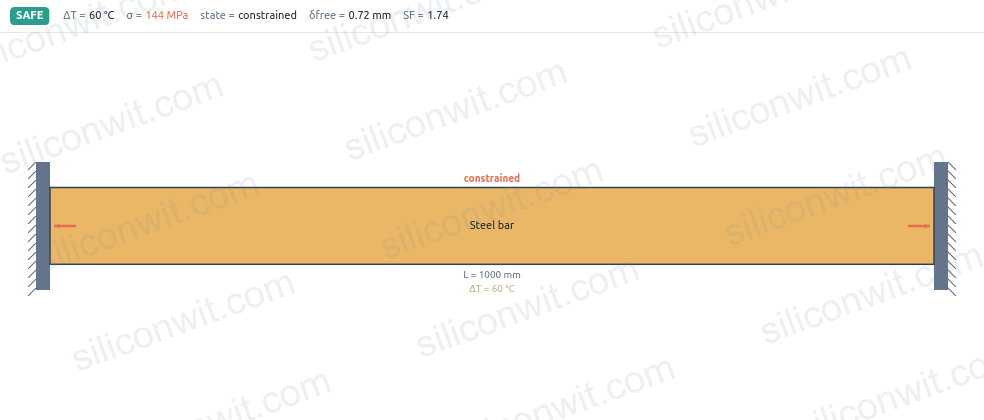
A steel actuator rod is rigidly clamped at both ends inside an aluminum housing. During a machine warm-up cycle the rod heats up by 60 °C. Because it cannot expand, it develops a compressive thermal stress.
Clamp a steel bar in the simulator and ramp the temperature to watch the thermal stress climb toward yield:
Compute the thermal strain:
Compute the free expansion over 500 mm:
This is the expansion the rod would undergo if neither end were fixed. Because both ends are clamped, the walls provide a reaction force that keeps the rod at its original 500 mm length. ✅
Thermal stress (the formula is independent of length):
Reaction force at each clamp:
Each clamp must carry 28.8 kN of compressive reaction even though no external load is applied to the rod. This force is invisible to a static load analysis but fully real. ✅
Compare the thermal stress with the yield strength:
Interpret the result. A safety factor of 1.74 is marginal for a real installation. If the temperature rise reached 90 °C (not unusual for a machine running hard) the stress would climb to
For a rod that must remain elastic across its full thermal range, either the material needs a higher yield strength, or the mounting must allow some axial movement (such as a slip fit with a soft spring return). ✅
An aluminum rod is pressed into a steel housing and pinned at both ends so the two parts must deform together. When the assembly heats up, aluminum tries to expand more than steel. The two materials fight each other: the aluminum is put in compression and the steel housing is put in tension by the same internal force.
Free expansion of the aluminum rod:
Free expansion of the steel housing:
Compatibility gap: aluminum wants to be 0.368 mm longer, steel wants to be only 0.192 mm longer. The pins force them to the same length, so neither gets what it wants:
An internal compressive force
Write the compatibility equation. Both parts must reach the same elongation
Rearrange to isolate
Compute the flexibility terms (working in N and mm, so
Solve for
Stress in the aluminum rod (compression, because it was forced to expand less than it wanted):
Stress in the steel housing (tension, because it was forced to expand more than it wanted):
Because the two areas are equal here, the stresses come out equal. In a real design the areas are usually different and the stresses differ accordingly. ✅
Common actual elongation (verify consistency):
Check via steel:
Yield check:
If the temperature rise were much larger, the aluminum would yield first because it has a lower yield strength. ✅
Match expansion coefficients
When two parts must maintain a precise fit across a temperature range, choose materials with similar
Provide room to grow
Expansion joints, slotted holes, and slip-fit ends let a member expand freely. A free member develops no thermal stress no matter how large the temperature change.
Check constrained stress against yield
Before welding or bolting a member into a rigid frame, compute
Account for thermal effects in tolerances
Clearances and press-fit interferences are room-temperature numbers. For any heated assembly, recalculate the fit at the operating temperature using the differential expansion before specifying the cold dimensions.
| Application | Description | Key result | Safety factor |
|---|---|---|---|
| Piston-cylinder (Al/steel) | differential expansion, | clearance grows from 0.05 mm to 0.092 mm | N/A (free expansion) |
| Fully restrained steel rod | 1.74 vs yield | ||
| Compound Al rod in steel housing | 5.9 (Al), 5.5 (st) |
All three analyses here used only
Next, Fundamentals of Shaft Torsion takes the same material-property framework into rotating shafts, where the load twists the cross-section rather than stretching or compressing it, and the governing stress is shear rather than normal.
Comments