Stiffness governs precision
In positioning systems, the deformation limit is often tighter than the strength limit. A shaft sized purely for strength may deflect several times more than the tolerance allows.
A CNC actuator shaft that stretches even a few micrometres under load throws off positioning accuracy, and choosing a material by cost alone risks either over-designing (heavy, expensive) or under-designing (flexible, imprecise). Selecting the right material requires comparing elastic modulus, yield strength, and elongation at failure across candidates, then computing the actual deformation under your expected loads. In this lesson you will perform that analysis on a CNC actuator shaft, read a steel tensile test curve to extract yield strength, toughness, and ductility, and compute shear deflection in a bonded elastomer mount. #AxialStress #MaterialSelection #CNCDesign
By the end of this lesson, you will be able to:
In a CNC machine the Z-axis actuator controls vertical tool movement. The shaft must transmit precise forces while maintaining dimensional accuracy under varying loads. A shaft that deflects too far under the cutting force moves the tool out of the programmed path, producing scrap.
Engineering Question: How do you select the right material and shaft diameter to ensure the CNC system maintains a deformation limit of 0.05 mm under a maximum axial load of 5,000 N?
Answering that requires two independent checks: a strength check (the stress must stay below the allowable strength) and a stiffness check (the elongation must stay within the positional tolerance). Either check can set the minimum diameter, and in precision systems the stiffness check almost always wins.
Stiffness governs precision
In positioning systems, the deformation limit is often tighter than the strength limit. A shaft sized purely for strength may deflect several times more than the tolerance allows.
Modulus sets deflection
Steel (
Section size follows from E
Because
Mass can be nearly equal
Steel is about 2.9 times denser than aluminum, but steel’s higher E lets it use a smaller cross-section, so the final shaft masses can end up similar.
The previous lesson defined stress. Here we build the quantities needed to predict deformation and to read a material test curve.
Axial Strain and Deflection
Where:
The second form is the most-used relation in this lesson: it links a known load and geometry to the actual elongation.
A tensile test pulls a standard coupon to fracture while recording force and extension. The resulting curve divides material behaviour into regions:
Key Points on the Curve
Energy Absorption Measures
Resilience measures how much elastic energy the material stores per unit volume before yielding. Toughness measures the total energy per unit volume absorbed before fracture, including all the plastic work.
Shear Modulus and Its Relation to E and Poisson's Ratio
Where:
For metals,
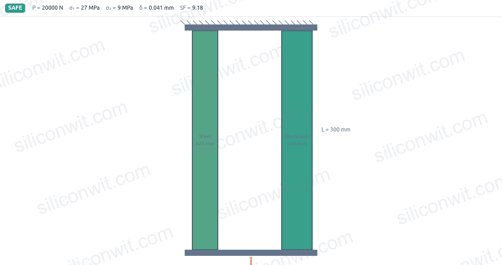
The CNC Z-axis shaft must transmit a maximum axial force of 5,000 N while keeping elongation within 0.05 mm over its 400 mm length. Both a strength check and a stiffness check are required.
Run the steel and the aluminum shaft as the A and B states in the simulator and compare the deflection directly:
Allowable stress for each material with SF = 3:
Aluminum:
Steel:
Minimum area from
Aluminum:
Steel:
Minimum diameter from
Aluminum:
Steel:
Strength alone would permit quite a thin shaft for either material. ✅
Required area from
Aluminum:
Steel:
(Here
Required diameter from
Aluminum:
Steel:
Compare the two criteria:
For aluminum: strength needs 8.4 mm, stiffness needs 27.0 mm. Stiffness governs by a factor of 3.2. ✅
For steel: strength needs 6.0 mm, stiffness needs 16.0 mm. Stiffness governs by a factor of 2.7. ✅
Confirm deformation for the stiffness-governed diameters. For the 27 mm aluminum shaft:
For the 16 mm steel shaft:
Estimate shaft mass using
Aluminum (
Steel (
The masses are nearly equal because steel’s higher density is almost exactly offset by its smaller cross-section. ✅
Design decision: Steel 1045 at 16 mm diameter meets both criteria, uses a 41% smaller diameter (16 mm versus 27 mm, which fits tighter machine envelopes), and has a similar mass to the aluminum option. ✅
A tensile test is the standard way to measure the mechanical properties of a material before it goes into a design. Understanding how to read the stress-strain curve lets you extract the numbers that feed every other analysis.
What “0.2% offset” means. Draw a straight line with slope equal to
Check the elastic slope at the yield point. At
The total strain at the 0.2% offset yield point is
Read the other landmarks:
Formula. The modulus of resilience is the area under the elastic portion of the curve, approximated as a triangle:
Calculation:
Meaning. This steel can absorb 306 kJ per cubic metre elastically before yielding. A material with higher resilience makes a better spring; higher toughness (see Step 3) makes a better crash absorber. ✅
Approach. The modulus of toughness is the total area under the stress-strain curve. A practical estimate splits the curve into the elastic triangle plus a trapezoidal plastic region:
where
Calculation:
Elastic contribution:
Average stress over plastic region:
Plastic strain range:
Plastic contribution:
Total:
Interpretation. The steel absorbs roughly 95 MJ per cubic metre before fracturing. Nearly all of that (99.7%) is plastic work during the large permanent elongation. This high toughness is what makes medium-carbon steel suitable for parts that must absorb impact without shattering. ✅
Percent elongation is defined over the original gauge length:
(The fracture elongation of 22% was read from the curve; it means the gauge section grew from 50 mm to 61 mm before breaking.) ✅
Classification. Materials with
Shear modulus governs any component that is loaded across its thickness rather than along its length. Bonded elastomer mounts are a common example: the rubber layer is glued between two metal plates, and when the structure moves horizontally the rubber is sheared. The mount’s compliance in shear is exactly what provides the vibration isolation.
Apply the elastic relation between
Context. For nearly incompressible materials such as rubber (
Shear stress is force over the area parallel to the load:
Check against the rubber’s short-term shear strength. Natural rubber typically carries shear stresses up to 1 to 2 MPa before tearing. At 0.125 MPa the mount is well within its elastic range. ✅
Shear strain from
Lateral shear deflection. Shear strain is the tangent of the shear angle, which for small angles equals
Interpret the result. A lateral deflection of about 1.9 mm under 800 N gives a lateral stiffness of
Check stiffness and strength separately
In precision systems, the deformation limit almost always sets a larger minimum cross-section than the strength criterion. Run both calculations and take the larger diameter.
Read the full stress-strain curve
Yield strength and UTS are on the same curve, but they mean different things. Yield is where permanent deformation begins; UTS is the peak load. Using UTS for a yield-based design check is unsafe.
Know G for shear-loaded parts
Any component carrying shear (a pin, an adhesive joint, a rubber mount, a splined coupling) requires the shear modulus, not Young’s modulus. Compute it from
Ductility provides failure warning
A material with more than 5% elongation at fracture deforms visibly before it breaks. This gives warning time. Brittle materials fracture suddenly, with no prior deformation, which is why ductility matters in safety-critical parts.
| Application | Key result | Governing criterion |
|---|---|---|
| CNC shaft: aluminum 27 mm, steel 16 mm | Al: | Stiffness governs both |
| Steel tensile coupon | Yield at 350 MPa, UTS 520 MPa | |
| Elastomer mount (80 mm x 80 mm, 20 mm thick) | Shear governs deflection |
Every number in this lesson came from three formulas (
Next, Compound Bars and Composite Systems extends the axial analysis to members made of two different materials in series or parallel, which is the situation in every bolted joint, press fit, and bi-material actuator.
Comments