Preventing shaft failure
Peak shear stress compared against the allowable value tells you whether the shaft survives the worst engagement torque before it is ever assembled.
A shaft that transmits torque without breaking can still fail functionally if it twists too much: the angular deflection throws off the timing in a Geneva indexing mechanism, causes vibration in a coupling, or misaligns a sensor mounting. Designing against torsional failure means checking both the shear stress (will it yield?) and the angle of twist (will it stay accurate?). In this lesson you will analyze three real cases, a Geneva mechanism crankshaft, a power-transmitting motor shaft, and a hollow-versus-solid shaft comparison, learning the torsion formula, polar moment of inertia, and the design trade-offs that keep rotating shafts strong and stiff. #Torsion #ShearStress #ShaftDesign
By the end of this lesson, you will be able to:
The Geneva mechanism converts continuous rotation into intermittent indexing motion. It appears in film-transport mechanisms, rotary indexing tables, and automated assembly equipment. The drive crankshaft spins continuously while the Geneva wheel advances one slot at a time, and every engagement event sends a torque spike through the crankshaft.
Engineering Question: How do we size the crankshaft so it can transmit peak torque without yielding, and keep the angular twist small enough to preserve timing accuracy?
Both criteria matter. A shaft that survives the stress but winds up by several degrees will cause the Geneva wheel to over-travel or under-travel its slot, jamming the mechanism or marking parts at the wrong position.
Preventing shaft failure
Peak shear stress compared against the allowable value tells you whether the shaft survives the worst engagement torque before it is ever assembled.
Preserving timing accuracy
The angle of twist formula sets how stiff a shaft must be so that angular deflection stays within the positioning tolerance of the driven mechanism.
Choosing solid versus hollow
Most of the torsional stiffness in a circular shaft comes from material near the outer surface, so removing the low-stress core saves weight with little penalty in strength.
Sizing for power transmission
Motors and gearboxes are specified by power and speed, not torque. Converting P and n to T is the first step in every shaft design.
When a circular shaft carries a twisting moment (torque), every cross-section resists by developing shear stress that varies linearly from zero at the centre to a maximum at the outer surface. Three formulas govern everything in this lesson.
Torsional shear stress
Where:
The stress is highest at the outer fibre because
Polar second moment of area
For a solid shaft of diameter
For a hollow shaft with outer diameter
Angle of twist
Where:
Angular deflection grows with torque and length, and shrinks with material stiffness and section stiffness. A shaft that passes the stress check can still fail the stiffness check if it is long or lightly proportioned.
Power and torque
A motor or gearbox rated at power
This is the gateway calculation for every driven shaft: convert the nameplate data to torque before applying the torsion formula.
The Geneva drive crankshaft below is the original motivating problem. Three design questions are answered in sequence: is the 25 mm shaft strong enough? if not, what diameter is needed for strength? and once resized, does it meet the timing requirement?
Apply the solid-shaft formula. Convert diameter to metres:
Store this value. It feeds directly into the stress and twist calculations that follow.
Continuous running stress:
Peak engagement stress:
The same result follows from the compact shortcut
Safety factor at peak torque:
The 25 mm shaft passes the strength check at SF = 3.7, above the required 3.0. ✅
Angle of twist under peak torque (
Converting to degrees:
Check against the precision requirement of
Required diameter for
Rounding up to the next standard size, 26 mm, meets both strength and stiffness requirements. ✅
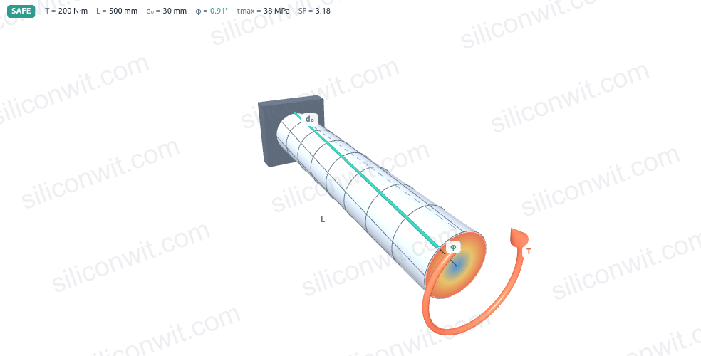
A small conveyor drive unit has a 5 kW induction motor running at 960 rpm. The output shaft connects the motor to a worm gearbox over a span of 400 mm. The shaft material is steel with
Enter the motor shaft in the simulator and read the peak shear stress and the angle of twist over its length:
Convert rotational speed to rad/s:
Compute the transmitted torque:
Polar second moment for the 20 mm solid shaft:
Peak shear stress at the outer surface (
Safety factor:
The shaft is safe. A factor of 1.89 is acceptable for a well-characterised steady load; if the drive sees shock loading or fatigue, a larger diameter would be chosen. ✅
Apply the twist formula (
Convert to degrees:
Over 400 mm the shaft twists by just under one degree. For a conveyor drive this is entirely acceptable. For a precision indexing shaft it would require a larger diameter to stiffen the section. ✅
A drive shaft must transmit
Minimum diameter from the allowable stress. Rearranging
Round up to the standard size:
Polar moment for the 26 mm solid shaft:
Shear stress check:
This is just below the 60 MPa allowable, confirming the sizing is correct. ✅
Cross-sectional area:
Polar moment for the hollow shaft (
Working out the fourth powers:
Peak shear stress at the outer surface (
The hollow shaft has a slightly lower peak stress than the solid shaft (55.1 MPa vs 58.0 MPa) despite having a larger outer diameter, because the additional outer material adds more
Cross-sectional area:
Area saving (which equals the mass-per-metre saving for the same material):
Summary side by side:
| Quantity | Solid, | Hollow, |
|---|---|---|
| Peak | 58.0 | 55.1 |
| Area (mm | 530.9 | 273.3 |
| Mass saving | baseline | 48.5% lighter |
Convert power to torque first
Every motor-driven shaft starts with
Check strength and stiffness separately
A shaft can pass the shear-stress check and still fail if the angle of twist throws off a timing mechanism or misaligns a coupling. Both criteria must be satisfied.
Increase diameter over length
Diameter enters
Consider hollow sections for weight
The centre of a shaft contributes little to torsional stiffness. For large diameters or weight-sensitive designs, hollow sections routinely save 40 to 60% of cross-sectional area with only a modest increase in outer size.
| Application | Key inputs | Peak | Angle of twist | Notes |
|---|---|---|---|---|
| Geneva crankshaft | 48.9 | 0.56° | Strength OK; stiffness marginally exceeded; use 26 mm | |
| Motor shaft | 31.7 | 0.92° over 400 mm | SF = 1.89; adequate for steady drive | |
| Solid shaft | 58.0 | |||
| Hollow shaft | 55.1 |
Every result in this lesson came from four formulas (
Next, Thin-Walled Pressure Vessels applies a similar two-stress approach to cylindrical shells, where internal pressure simultaneously creates both hoop (circumferential) and longitudinal normal stresses in the wall.
Comments