Predicting failure
Stress compared against the material’s strength tells you whether a part survives its worst load, before it is ever built.
A connecting rod that looks strong enough can fail in service if the designer did not account for the stress concentration at a fillet, the fatigue limit of the material, or the difference between tensile and compressive loading. Predicting whether a part will survive requires more than intuition: it requires stress analysis. In this lesson you will learn the fundamental quantities (stress, strain, Young’s modulus, Poisson’s ratio) and put them to work on three real parts, the connecting rod in a crank-slider mechanism, a precision tie rod in tension, and a clevis pin in double shear. #StressAnalysis #MechanicsOfMaterials #ConnectingRod
By the end of this lesson, you will be able to:
Consider an internal combustion engine or a reciprocating compressor. At the heart of these systems lies the crank-slider mechanism, one of the most fundamental motion conversion systems in mechanical engineering. The connecting rod ties the rotating crank to the sliding piston, and on every compression stroke it carries a large axial load that switches between compression and tension thousands of times a minute.
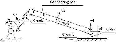
Engineering Question: During the compression stroke, enormous forces act on the connecting rod. How do we know the rod will not buckle, yield, or break, and how much will it deform under load?
Answering that needs more than a feel for “strong enough.” Without stress and strain we cannot predict whether the rod will fail, choose between steel, aluminum, and titanium, optimize the cross-section, or guarantee reliable operation over millions of cycles.
Predicting failure
Stress compared against the material’s strength tells you whether a part survives its worst load, before it is ever built.
Material selection
Young’s modulus and yield strength let you trade steel against aluminum or titanium on stiffness, weight, and cost.
Sizing the section
Because stress is force over area, the analysis sets the smallest cross-section that is still safe, which controls weight.
System reliability
In a mechatronic system a single mechanical failure stops everything, so the load-bearing parts decide overall reliability.
With the reason for the analysis clear, we can build the four quantities that the rest of the chapter rests on.
Stress is the internal resistance of a material to applied force, measured as force per unit area:
Normal Stress
Where:
The same force over a smaller area gives a higher stress. This single idea, force spread over area, is the most-used relation in the whole subject.
Normal stress (
Shear stress (
Stress is measured in pascals:
The relation 1 MPa = 1 N/mm² is worth memorizing: it lets you work in newtons and millimetres and read the answer straight off in MPa.
Typical yield strengths: structural steel 250 to 400 MPa, aluminum alloys 70 to 500 MPa.
Strain measures deformation: how much a material changes length relative to its original size.
Normal Strain
Where:
Strain is a ratio, so it has no units. A strain of 0.001 means the part stretched by one part in a thousand, often written as 1000 microstrain.
For most engineering materials, up to a limit, stress and strain are proportional:
Hooke's Law
Where
Young’s modulus is a measure of stiffness: how much stress is needed to produce a given strain.
When a bar is stretched along its length, it gets thinner across its width. Poisson’s ratio links the two:
Poisson's Ratio
Where:
The minus sign makes
Return to the crank-slider and put the theory to work on the rod itself.
Apply the stress formula. Work in newtons and square millimetres so the answer falls out in MPa:
Read the result. The rod carries a peak compressive stress of 30 MPa, well below the 350 MPa yield strength of steel. ✅
Compare the stress with the yield strength:
Interpret it. A static safety factor of 11.7 looks generous, and against a single static load it is. A connecting rod is not sized by static yield, though: it is sized by fatigue (millions of load reversals) and by buckling under compression. The large static margin is what those other limits leave behind, not over-design. ✅
Find the strain from Hooke’s law:
Find the shortening:
The rod shortens by about 23 micrometres under peak load, negligible for engine geometry but exactly the kind of number that matters in a precision positioning system, as the next application shows. ✅
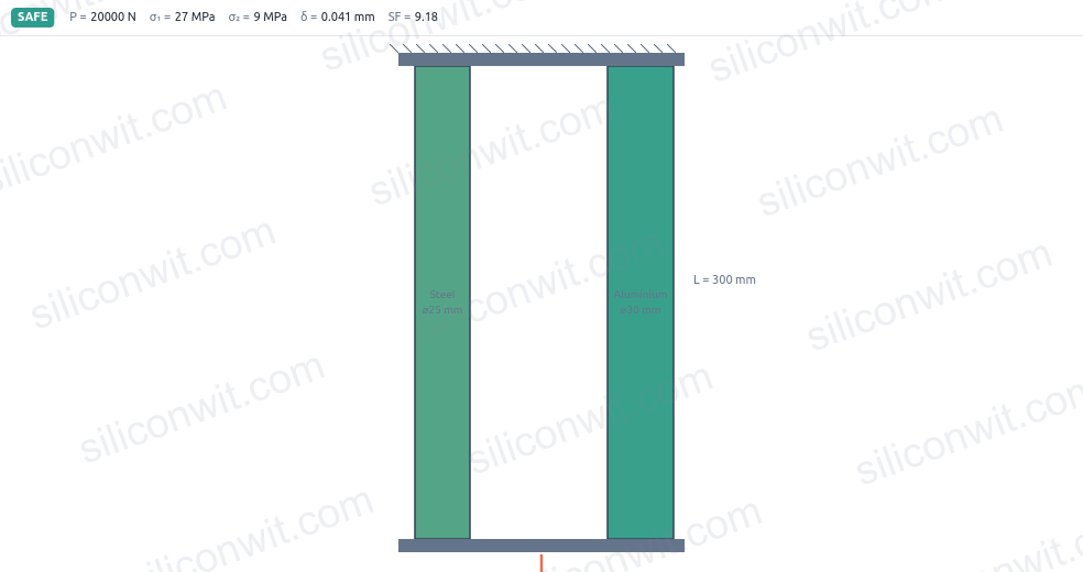
A camera gantry, a CNC frame, and many robot structures use a thin steel tie rod (or turnbuckle) to hold two points at a fixed spacing under tension. Here both the stretch and the sideways contraction matter, because the tie rod also acts as a dimensional reference.
Set a single steel bar to these values in the simulator and confirm the stress and elongation match the hand calculation below:
Cross-sectional area of the round rod:
Tensile stress:
Safety factor against yield:
A safety factor of 3.4 is sensible for a static structural tie with well-known loads. ✅
Longitudinal strain:
Elongation:
The rod stretches about 0.31 mm. On a gantry that positions a tool or camera, three tenths of a millimetre is the difference between in-tolerance and scrap, so this stretch must be designed in. ✅
Lateral strain follows from Poisson’s ratio:
Change in diameter:
The rod necks down by about 1.5 micrometres while loaded. It is tiny, but it is real, and in a press fit or a threaded joint that contraction can be enough to loosen a connection under load. ✅
Where one link of a robot or a linkage connects to another, the load usually passes through a pin. A clevis (a forked fitting) grips the pin on two sides, so the pin is cut across by two shear planes at once. This is double shear, and it is governed by shear stress rather than normal stress.
Identify the shear planes. In double shear the load is carried by two cross-sections of the pin, so the area resisting shear is twice the single area:
Shear stress:
If the same pin were in single shear, the stress would double to about 119 MPa. Putting the pin in double shear halves the shear stress, which is why clevis joints are used for higher loads. ✅
Estimate the shear yield strength. A ductile metal yields in shear at roughly
Safety factor:
The pin has a comfortable margin. The more conservative maximum-shear-stress theory uses
Steel (structural)
Aluminum (6061-T6)
Carbon fiber composite
Start with force over area
Most static checks reduce to
Check strength and stiffness
A part must pass two tests: the stress stays below the allowable strength, and the deflection stays within tolerance. Either one can govern.
Know which stress acts
Normal stress and shear stress fail differently. Identify whether the load stretches, compresses, or cuts the section before choosing the formula.
Remember the side effects
Poisson contraction, fatigue, and buckling all hide behind a clean static number. A generous static safety factor does not excuse you from checking them.
| Application | Load type | Key result | Safety factor |
|---|---|---|---|
| Connecting rod | compression | 11.7 (static) | |
| Tie rod | tension | 3.4 | |
| Clevis pin | double shear | 3.4 |
Every result here came from three formulas (
Next, Strain and Mechanical Properties develops the full stress-strain curve, the difference between stiffness and strength, and how a material’s behaviour past the elastic limit decides whether a part bends or breaks.
Comments