Predicting failure mode
The 2:1 ratio between hoop and longitudinal stress tells you the vessel splits lengthwise first. Getting the ratio wrong means the wrong weld seam orientation, the wrong inspection plane, and an unconservative design.
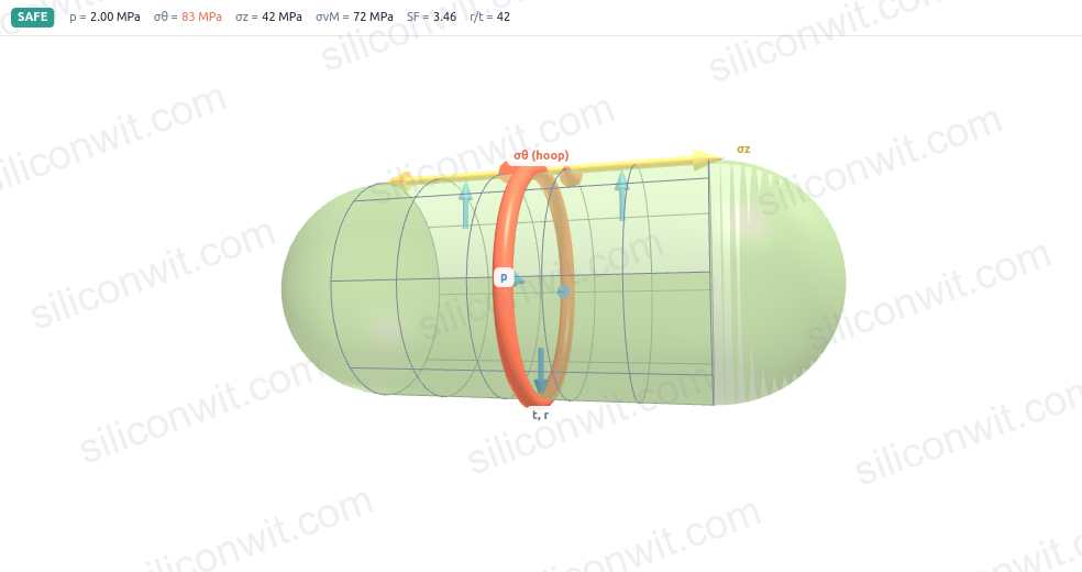
A pneumatic actuator casing that is too thin ruptures under pressure; one that is too thick wastes material, adds weight, and costs more. Unlike a solid bar in tension, a pressurized cylinder develops two distinct stresses simultaneously: hoop stress around its circumference and longitudinal stress along its axis. The hoop stress is always twice the longitudinal, which is why cylindrical vessels split lengthwise rather than across. A sphere, by contrast, carries the same stress in every direction at the wall, and that symmetry means it needs only half the wall thickness of a cylinder at the same pressure. In this lesson you will calculate both stresses, size wall thickness for a given pressure and material, and see the sphere advantage proved by numbers. #PressureVessels #HoopStress #PneumaticDesign
By the end of this lesson, you will be able to:
Pneumatic actuators drive grippers, clamps, slides, and valves throughout industrial automation. The cylindrical casing contains pressurized air at every working moment, so a stress error in the wall is not a performance issue but a safety issue.
Engineering Question: How do we determine the minimum wall thickness for a pneumatic actuator casing operating at 0.6 MPa gauge pressure, and what stresses does that wall actually carry?
Without a stress model, “thick enough” is guesswork. With it, you can choose the wall thickness, predict the failure mode (lengthwise splitting, not end-cap blowout), pick the right safety factor, and prove compliance to a pressure-vessel code.
Predicting failure mode
The 2:1 ratio between hoop and longitudinal stress tells you the vessel splits lengthwise first. Getting the ratio wrong means the wrong weld seam orientation, the wrong inspection plane, and an unconservative design.
Sizing wall thickness
Because hoop stress governs, the minimum wall thickness comes directly from the hoop formula. Setting that thickness correctly prevents both under-design (burst) and over-design (excess mass and cost).
Material and geometry tradeoffs
Cylinder versus sphere at the same pressure and radius: the sphere wall stress is half the cylinder hoop stress, so the sphere needs half the wall. Knowing this guides vessel shape selection from the start.
Code compliance
Pressure vessel standards (ASME, ISO 4393) mandate specific safety factors. The analysis here is the calculation the code is built on, and you cannot fill in a compliance form without it.
Thin-Wall Assumption
The thin-wall formulas apply when the radius-to-thickness ratio satisfies:
Below this ratio the stress varies noticeably across the wall thickness and thick-wall (Lame) equations are needed. Above it, the stress is nearly uniform across the wall and the two simple formulas below are accurate to within a few percent.
Hoop (Circumferential) Stress in a Cylinder
Cut the cylinder lengthwise through a diameter. Internal pressure
Where
Longitudinal (Axial) Stress in a Cylinder
Cut the cylinder across its axis. Pressure
This is exactly half the hoop stress. The cylinder is therefore in biaxial stress:
Stress in a Spherical Vessel
Any diametral cut through a sphere gives a symmetric result. Pressure
The sphere wall stress equals the cylinder longitudinal stress and is half the cylinder hoop stress. For the same pressure, radius, and wall thickness, the sphere wall is loaded to half the stress of the cylinder wall.
A compact pneumatic gripper casing is the starting point: a cylinder that must contain working pressure while staying light enough to be end-of-arm tooling.
Set the allowable stress. The hoop stress must not exceed the yield strength divided by the safety factor:
Solve for minimum thickness. From
Select a standard thickness. A 3.0 mm wall is the nearest standard aluminum sheet with adequate margin for machining tolerances and stress concentrations around ports. ✅
Hoop stress:
Longitudinal stress:
Safety factors with the chosen wall:
Both well above the required 4.0. ✅
Why is the margin so large? The minimum calculated wall is only 0.44 mm, but a 3.0 mm wall is 6.8 times thicker. This is not over-design: the 3.0 mm wall is the thinnest practical aluminum sheet for a machined casing with threaded port holes, corrosion allowance, and port-hole stress concentrations (which locally multiply the nominal stress by a factor of 2 to 4). ✅
What the numbers confirm. The hoop stress governs (10.0 MPa vs 5.0 MPa longitudinal), the vessel would split lengthwise before blowing an end cap, and the static margin is more than adequate. A fatigue check against cyclic pressure remains a separate step for high-cycle applications. ✅
A compressed-air receiver stores energy between the compressor and the distribution network. It is a plain cylindrical vessel at a higher pressure than typical pneumatic actuators, with no ports other than an inlet and an outlet, so the nominal wall stress is the governing calculation.
Set this cylinder in the simulator and read the hoop and longitudinal stresses and the safety factor:
Check
This is well above the threshold of 10, so the thin-wall formulas apply. ✅
Hoop stress:
Longitudinal stress:
Confirm the 2:1 ratio.
Safety factor of the 10 mm wall against yield:
The wall carries the hoop stress at safety factor 10.9 against first yield. This is typical for a receiver tank sized to a pressure-vessel code with corrosion allowance and cyclic loading. ✅
Allowable stress for SF = 4.0:
Minimum wall thickness at SF = 4.0:
A 10 mm wall is about 2.7 times the physics minimum at SF = 4.0. The extra thickness accounts for corrosion allowance (typically 1 to 2 mm for a steel receiver), manufacturing tolerance, and the conservative margins that pressure-vessel inspection codes require. ✅
Large gas storage spheres appear at refineries, LPG terminals, and compressed-gas facilities. The sphere shape is chosen for a direct mechanical reason: at the same internal pressure and radius, the wall stress in a sphere is exactly half the hoop stress in a cylinder. That means about half the wall thickness for the same duty, which matters when the vessel weighs hundreds of tonnes.
Apply the sphere formula. For a spherical shell any diametral cut gives the same result:
Compare with the cylinder. At identical
The sphere wall carries exactly half the stress of the cylinder hoop, because the sphere distributes the pressure force over the full circumference in both directions simultaneously. ✅
Safety factor of the 10 mm sphere wall:
With the same 10 mm wall, the sphere operates at safety factor 21.9 against first yield, compared to 10.9 for the cylinder. The sphere can therefore use a thinner wall while achieving the same safety factor. ✅
Allowable stress (same as Application 2):
Minimum sphere wall thickness:
Compare with the cylinder minimum (Application 2): 3.66 mm.
The sphere needs precisely half the wall thickness of the cylinder at the same pressure, radius, and safety factor. This is not a coincidence: it follows directly from the factor of 2 in the stress formulas. ✅
Always use radius, not diameter
The formulas
Hoop stress governs cylinder design
In a cylinder, size the wall for hoop stress. The longitudinal stress will then automatically have a safety factor twice as large. A vessel designed only for longitudinal stress is under-designed by a factor of two.
Verify the thin-wall assumption
Confirm
Select standard wall with practical margin
The physics minimum from
| Application | Geometry | SF (as built) | |||
|---|---|---|---|---|---|
| Pneumatic actuator casing | Cylinder | 10.0 MPa | 5.0 MPa | 27.0 | 0.44 mm |
| Compressed-air receiver | Cylinder | 32.0 MPa | 16.0 MPa | 10.9 | 3.66 mm |
| Spherical accumulator | Sphere | 16.0 MPa | 16.0 MPa | 21.9 | 1.83 mm |
The sphere at the same
All three calculations used the same two formulas and arithmetic with millimetres and megapascals. For a new vessel design, a spreadsheet covering
This lesson closes Chapter 1. The principles here (force divided by a resisting area, a stress compared against an allowable, a geometry that determines which direction carries more load) carry directly into the beam problems in Chapter 2. The next step is Shear Force and Bending Moment in Beams, where internal pressure is replaced by transverse loading and the resisting area becomes a cross-section in bending.
Comments