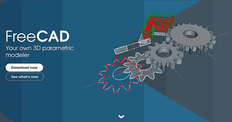
Copying a shape at a different scale by hand is slow and error-prone, and resizing with software distorts curves unless you control the transformation carefully. A pantograph uses similar triangles to scale motion mechanically with zero distortion, which is why it has been used for centuries in engraving, map duplication, and precision manufacturing. Changing the pivot position changes the scale ratio, making it a natural fit for parametric CAD where a single dimension drives the entire geometry. In this lesson you will design a pantograph in FreeCAD with expression-based parametric control over the scaling ratio. #FreeCAD #Pantograph #MotionScaling #SimilarTriangles
Learning Objectives
By the end of this lesson, you will be able to:
Design mechanisms based on ratio relationships and similar triangle geometry
Implement expressions to link multiple dimensions mathematically
Create master sketch approach for coordinated multi-part design
Control motion scaling with single parameter (scaling ratio k)
Verify geometric relationships through parametric testing
Engineering Context: Why This Mechanism Matters
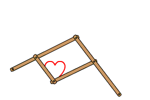
A pantograph is an elegant mechanical linkage that scales motion through similar triangle geometry. It can enlarge, reduce, or exactly copy a path traced by one point as output at another point, with applications ranging from engraving to drafting tools.
Real-World Applications
The pantograph appears in diverse engineering applications:
The Engineering Problem
Design Challenge: Given a path traced by an input stylus or pointer, reproduce that path at a different scale while maintaining geometric similarity and smooth motion.
Part Design - Creating individual parametric parts
Sketcher - Creating 2D constraint-based sketches
Spreadsheet - Parameter tables with formulas
Assembly - Combining parts with constraints
TechDraw - Creating engineering drawings
Part 2: Parametric Design Strategy
The pantograph is our first ratio-driven mechanism where geometric relationships are more complex. We’ll use a master sketch to define the kinematic layout, then reference it from all parts. This ensures geometric consistency and simplifies the parametric control to just two values: base length and scaling ratio.
Our Design Approach
🎯 Ratio-Based Control Philosophy
We’ll control the entire pantograph mechanism with just two parameters:
BaseLength = 100 mm
ScalingRatio = 2
All other dimensions calculated automatically using expressions!
No need to draw anything - the origin marker is already there!
First base link:
Line tool (press L)
Click at origin (0, 0)
Draw at approximately 45° upward-right
Click to place endpoint
Press Escape
Add length constraint:
Distance/Length constraint tool
Click the line
Click ƒx button
Type: Spreadsheet.BaseLength
Enter
Add angle constraint:
Angle constraint tool
Click the line
Type: 45 (degrees from horizontal)
Enter
Label this endpoint mentally as “A”
Second base link:
Line tool
Click at origin
Draw horizontally to the right
Click to place endpoint
Escape
Make horizontal:
Select the line
Press H key (or apply Horizontal constraint)
Add length constraint:
Distance constraint
Click the line
ƒx → Spreadsheet.BaseLength
Enter
Label this endpoint as “B”
Connecting link:
Line tool
Connect point A to point B
Escape
Add length constraint:
Distance constraint
Click the line
ƒx → Spreadsheet.CrossLink
Enter
This forms triangle OAB - the core parallelogram structure!
Extension to input point:
Line tool
Start at A (endpoint of OA)
Draw along the same 45° angle (extending OA)
Click to place endpoint
Escape
Collinear constraint:
Select the new line
Select line OA
Apply Collinear constraint
This ensures they’re on the same line!
Total distance O to I:
Distance constraint
Click origin
Click far endpoint (point I)
ƒx → Spreadsheet.InputLength
Enter
Extension to output point:
Line tool
Start at B
Draw horizontally right (extending OB)
Click to place endpoint
Escape
Collinear constraint:
Select new line and line OB
Apply Collinear constraint
Total distance O to P:
Distance constraint
Origin → far endpoint (P)
ƒx → Spreadsheet.OutputLength
Enter
Make everything reference geometry:
Press Ctrl+A to select all geometry
Press G to toggle construction mode
All lines turn blue/dashed - they’re now construction geometry
Optional: Add small circles (radius 2mm) at points O, A, B, I, P for visualization
Check the solver:
Should show: “Fully constrained”
What’s defined:
O is at origin (coincident)
OA length and angle (45°)
OB length and horizontal
AB length (cross link)
OI total length (input arm)
OP total length (output arm)
Close the sketch
Click Close button in toolbar
Rename for clarity
Find “Sketch” in the tree
Right-click → Rename → MasterSketch
Master sketch complete! This defines all key points for the entire mechanism.
Part 5: Creating Link OA
Design Intent
⚙️ Link OA Requirements
Link from fixed pivot O to moving pivot A:
Holes at O and A for pin joints
Rectangular body connecting the holes
References master sketch for exact positioning
Step-by-Step: Link OA
Create Body
Part Design workbench
Click Create Body button
Right-click → Rename → Link_OA
Create Sketch
Select Link_OA body
Create Sketch → XY_Plane
Reference master sketch points
Click External Geometry tool (or press E)
In the tree, find and select MasterSketch
Click on points O and A in the 3D view
They appear as purple reference points
Draw the link profile
Circle at point O: Radius constraint → ƒx → Spreadsheet.PinRadius
Circle at point A: Radius constraint → ƒx → Spreadsheet.PinRadius
Rectangle connecting them, symmetric about the OA line
Width dimension: ƒx → Spreadsheet.LinkWidth
Close sketch
Pad the link
Select the sketch
Click Pad tool
Length: ƒx → Spreadsheet.LinkThickness
OK
Link OA complete!
Part 6: Creating Link OB
Same process as Link OA, but reference points O and B:
Body: Create and rename to Link_OB
Sketch on XY_Plane
External Geometry:
Reference MasterSketch
Select points O and B
Draw profile:
Circles at O and B (PinRadius)
Rectangle connecting them (LinkWidth)
Pad: LinkThickness
Link OB complete!
Part 7: Creating Link AB
The connecting link between moving pivots A and B:
Body:Link_AB
Sketch on XY_Plane
External Geometry:
Reference MasterSketch
Select points A and B
Draw profile:
Circles at A and B (PinRadius)
Rectangle body (LinkWidth)
Pad: LinkThickness
Link AB complete!
Part 8: Creating Input Arm (OI)
Design Intent
📍 Input Arm Purpose
This arm extends from O through A all the way to I (input stylus):
Pivot at O (shares with base links)
Passes through A (coordinates with Link OA)
Extends to I (input point for user to control)
Stylus holder at point I
Step-by-Step: Input Arm
Body: Create and rename to InputArm
Sketch on XY_Plane
External Geometry:
Reference MasterSketch
Select points O, A, and I
Draw arm profile:
Long rectangle from O to I
Holes at O and A for pin joints (PinRadius)
Width: LinkWidth (or slightly narrower if needed)
Stylus holder at I: Small protrusion or marking hole
Pad: LinkThickness
Input Arm complete!
Part 9: Creating Output Arm (OP)
This arm extends from O through B to P (output tracer).
Step-by-Step: Output Arm
Body:OutputArm
Sketch on XY_Plane
External Geometry:
Reference O, B, and P
Draw arm profile:
Rectangle from O to P
Holes at O and B (PinRadius)
Width: LinkWidth (or narrower)
Tracer mount at P: Protruding pin or marking feature
Pad: LinkThickness
Output Arm complete!
Part 10: Creating the Base
Design Intent
⚓ Base Requirements
Fixed mounting plate providing:
Pivot mount at O for all rotating links
Stable foundation for the mechanism
Mounting holes for securing to work surface
Step-by-Step: Base
Create Body
Body: Base
Create Sketch on XY_Plane
Draw base plate:
Rectangle centered at origin
Width: 150 mm
Height: 100 mm
Use Symmetric constraints to center about X and Y axes
Add pivot hole at O:
Circle at origin
Radius: ƒx → Spreadsheet.PinRadius
Optional: Add mounting holes
Four circles in corners for bolt holes
Radius: 4 mm (M8 clearance)
Position: 10mm from edges
Check: Fully constrained
Pad: Thickness = 15 mm
Base complete! All parts are now ready for assembly!
Part 11: Assembly
Assembly is where the pantograph comes to life! With six separate parts all sharing a common pivot point at O, proper constraint strategy is critical. We’ll use axial alignment to create revolute joints while maintaining the parallelogram geometry.
Assembly Strategy
🎯 Assembly Constraints Plan
Base: Fixed (ground link)
Four links pivot at O: Link_OA, Link_OB, InputArm, OutputArm
The true test of a pantograph is its scaling accuracy. We’ll verify both the geometric construction and the parametric control to ensure the mechanism works correctly at any scaling ratio.
✅ Success indicator: Output displacement = k × Input displacement
Change the scaling ratio:
Open Spreadsheet
Double-click Spreadsheet in tree
Change ScalingRatio
Click cell B2
Change from 2 to 3
Press Enter
Recompute
Press Ctrl+R or click Recompute button
Observe automatic updates:
InputLength now = 300mm (100 × 3)
OutputLength now = 900mm (100 × 3²)
CrossLink now = 300mm
All parts update geometry!
Assembly adjusts automatically!
Test motion again
Move input 10mm
Output should now move 30mm (3× input)
✅ This is parametric design power!
Verify the math:
For a pantograph with scaling ratio k:
If input point I is at (x, y) relative to O,
Then output point P is at (k×x, k×y) relative to O
Example with k = 2:
Input moves to I = (50, 50) mm
Output should be at P = (100, 100) mm
Test this:
Position input at I = (50, 50)
Measure P coordinates
Verify P = (100, 100)
Part 13: Technical Drawing
Creating Professional Documentation
Switch to TechDraw workbench
Use workbench dropdown
Create a page
Insert Page
Choose template: A3_Landscape
Add assembly view
Insert View → Select assembly
Position: Front view showing full mechanism
Scale: 1:2 or 1:1 depending on size
Add dimensional callout
Create text box showing:
Scaling Ratio:
Link Lengths:
Add motion diagram (optional)
Show two positions of mechanism
Dimension: ΔI = 10mm, ΔP = 20mm
Demonstrates scaling relationship
Title block
Part name: “Pantograph Mechanism”
Scaling ratio:
Scale, date, your name
Export
Right-click page → Export as PDF
You now have professional documentation for your parametric pantograph!
Part 14: Testing Parametric Control
This is where expression-based parametric design really shines. Watch as a single parameter change recalculates all dependent dimensions and updates the entire mechanism automatically.
Comments