Every internal combustion engine, every reciprocating compressor, and every hand-operated water pump relies on the same kinematic chain: a crank, a connecting rod, and a slider. Despite its simplicity, the mechanism’s behavior changes significantly when you adjust the crank-to-rod ratio or add an offset, and predicting those changes from a sketch alone is difficult. In this lesson you will build a complete slider-crank mechanism in FreeCAD from scratch, with parametric dimensions that let you explore how link lengths affect stroke, velocity, and mechanical advantage. #FreeCAD #SliderCrank #ReciprocatingMotion #KinematicDesign
Learning Objectives
By the end of this lesson, you will be able to:
Navigate the FreeCAD interface and understand workbenches
Create fully constrained 2D sketches with geometric and dimensional constraints
Build parametric 3D parts controlled by spreadsheet parameters
Assemble multi-part mechanisms with motion constraints
Generate professional technical drawings for documentation
Engineering Context: Why This Mechanism Matters
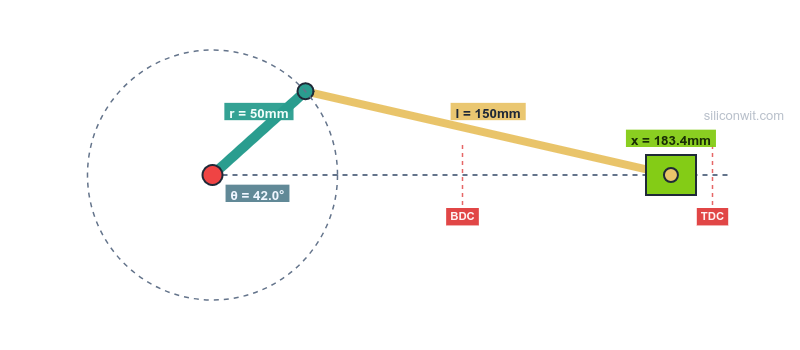
The slider crank mechanism is one of the most fundamental and widely used motion conversion mechanisms in mechanical engineering. It converts continuous rotational motion into reciprocating linear motion (or vice versa), powering everything from internal combustion engines to reciprocating compressors and pumps.
Real-World Applications
The slider crank appears everywhere in engineering:
The Engineering Problem
Design Challenge: Given a rotating crankshaft, how do we create linear reciprocating motion with controlled stroke length and predictable motion characteristics?
Mechanism Fundamentals
Components and Motion
A slider crank consists of four elements working together:
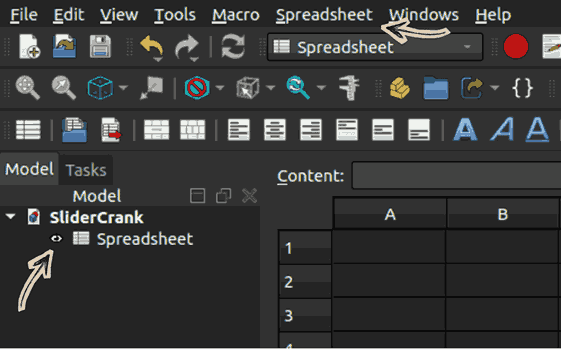
When you first open FreeCAD, you’ll see four key areas:
Top toolbar
Workbench selector (dropdown)
Common tools and commands
Left sidebar (Model Tree)
Shows all objects in your document
Hierarchical organization
Click to select, double-click to edit
Center (3D Viewport)
Where you see and interact with your model
Navigate in 3D space
Primary design area
Bottom (Report View)
Console messages
Python console access
Error reporting
🔧 What Are Workbenches?
FreeCAD organizes tools into workbenches - specialized tool collections for different tasks. Think of them as different “modes” optimized for specific workflows.
Key Workbenches for This Lesson:
Part Design - Creating individual parametric parts (primary workbench)
Sketcher - Creating 2D constraint-based sketches
Spreadsheet - Parameter tables and calculations
Assembly - Combining parts with constraints
TechDraw - Creating engineering drawings
Essential Navigation Controls:
Action
Control
Rotate view
Middle mouse button + drag or Shift + Right mouse button
Pan view
Shift + Middle mouse button + drag
Zoom
Mouse wheel scroll
Fit all
Press “V” then “F”
View front
Press “1” on numpad
View top
Press “7” on numpad
Practice Now!
Spend 2 minutes navigating the empty 3D view using these controls. Muscle memory now saves time later!
Part 2: Parametric Design Strategy
Unlike direct modeling where you just “draw shapes,” parametric design means defining design intent through relationships, controlling geometry with parameters, and ensuring changes propagate correctly throughout your model. This is how professionals design—build it once, change it instantly.
Our Design Approach
🎯 Two-Parameter Control Philosophy
We’ll control the entire slider crank mechanism with just two parameters:
CrankRadius = 30 mm
RodLength = 100 mm
Change these two values → entire mechanism updates automatically!
Click the outer circle, then press ‘K’ and ‘R’ in quick succession to activate the Radius Constraint Dimensioning Tool (or go to Sketch → Sketcher Constraints → Constrain Radius).
Type 40
Click OK.
Crank disk is now 40mm radius.
Click the inner circle, then press ‘K’ and ‘R’ in quick succession
Type: 8
Press Enter
8mm radius shaft hole created.
Click the offset circle, then press ‘K’ and ‘R’ in quick succession
Type: 5
Press Enter
5mm radius pin hole created.
🎯 Critical Parametric Link
This is where it gets powerful!
Click the origin point, then click the origin point of the Rod Pin Hole circle.
Press ‘L’ to activate the Constraint Horizontal Distance Dimensioning Tool. Don’t type a number!
Click the small fx button and in the formula editor, start typing Spreadsh… and <<Spreadsheet>> will appear. Then, click it. Next, start typing the alias Crank… and CrankRadius will appear. Click it.
Click OK and you will see Radius: 30.00.
Click OK again.
Magic! The dimension now shows “30mm” and will update whenever you change the spreadsheet!
Finalizing the Sketch
Check the solver
Look at “Solver Messages” panel (left side):
Should say “Fully constrained”
If it says “X degrees of freedom”, you’re missing constraints
Close the sketch
Click the Close button in the toolbar
The sketch is now a 2D profile visible in the 3D view
Using external geometry guarantees perfect alignment with the outer profile.
Cut through the body:
Close sketch
Select one hole circle sketch
If hidden, click the eye icon or double-click the sketch
Click Hole tool
Depth: Through all
Diameter: R × 2
OK
Repeat for the second hole
Press V, F → View Fit
Save: Ctrl + S
Connecting rod complete and fully parametric!
Part 6: Creating the Slider
Design Intent
The slider is a block that moves linearly, with a hole for the connecting rod pin.
Quick Creation Steps
Hide the ConnectingRod by clicking the eye
Body: go to Part Design → Create Body, then rename to Slider
Sketch on XY_Plane:
Sketch: Click Slider, then go to Sketch → Create Sketch, click XY-Plane
Rectangle: Press G, R, then click an arbitrary location to draw a rectangle, then Escape or right click
Symmetric constraints: Click top right corner, then bottom left corner, then click origin, then press S to center the rectangle about X and Y axes
Length Dimension: Click the bottom left corner, then the bottom right corner, then press L, then enter Length = 40 mm
Height Dimension: Click the bottom left corner, then the top left corner, then press I, then enter Height = 30 mm
Check: Fully constrained, then close the sketch
Pad: Length = 20 mm
Circle: At origin for pin hole
Click the pad and select the top face
Go to Sketch → Create Sketch
Press G, C to draw a circle of an arbitrary radius starting from the origin within the slider block, then right click or Escape
Click the circle arc, press K, R, then enter radius 10 mm (arbitrary within the block to achieve a fully constrained sketch), and close the sketch
Click the Hole tool, set depth to Through all, and diameter to be 12 mm, then OK
Press CRTL + S to save your part design
Slider complete!
Part 7: Creating the Frame
Design Intent
The frame provides:
Pivot mount for the crank
Linear guide for the slider
Creating the Frame
Body:Frame
Sketch on XY_Plane:
Rectangle below origin: 160mm × 20mm
Circle at origin: radius = 8 mm (crank pivot)
Optional: Add slider guide features (rails)
Pad:15 mm
Frame complete!
All four parts are now ready for assembly!
Part 8: Assembly
Assembly is where your individual parts come together as a functioning mechanism. FreeCAD’s Assembly workbench uses constraints to define how parts relate to each other, allowing you to test motion and verify your design before manufacturing.
Assembly Strategy
🎯 Assembly Constraints Plan
Frame: Fixed (ground link)
Crank: Rotates about fixed pivot at origin
Connecting Rod: Pivots on crank pin and slider pin
This aligns the axes and allows rotation! Crank can now spin about its shaft.
Connect rod to crank:
Rod left hole axis → Crank offset pin hole axis
Axial Align constraint
Connect rod to slider:
Rod right hole axis → Slider pin hole axis
Axial Align constraint
Constrain slider to linear motion:
Select slider bottom face
Select frame top face
Apply Plane coincident or Linear constraint
This keeps slider on the guide!
Test the mechanism:
Try dragging the crank in the assembly view:
Crank should rotate
Rod should follow
Slider should move linearly!
Part 9: Technical Drawing
Creating Professional Documentation
Switch to TechDraw workbench
Create a page:
Insert Page
Choose template: A4_Portrait
Add views:
Insert View → Select Crank body
Position the view by dragging
Add dimensions:
Use Dimension tools: Horizontal, Vertical, Radius
Click features to dimension them
Title block:
Double-click text fields
Enter: Part name, material, scale, your name, date
Export:
Right-click page → Export as PDF
You now have professional engineering documentation!
Part 10: Testing Parametric Control
This is the moment of truth! A truly parametric model updates correctly when you change parameters. Let’s verify your design is intelligent and responsive.
Comments