Master parametric CAD design by creating a toggle clamp mechanism, one of manufacturing’s most essential fixturing devices. Learn FreeCAD through real-world over-center linkage design with self-locking behavior. #FreeCAD #ToggleClamp #OverCenter #SelfLocking
🎯 Learning Objectives
By the end of this lesson, you will be able to:
Design mechanisms with angle-based constraints and over-center geometry
Create clearance-aware parametric parts with motion limits
Implement mechanical advantage through intelligent linkage design
Control locked and unlocked states via geometric relationships
Generate functional drawings showing multiple mechanism positions
🔧 Engineering Context: Why This Mechanism Matters
Tog gle cla mps are essen tial fixtu ring devi ces th at us e ov er-cen ter geom etry to cre ate hi gh clam ping for ces with lo w inp ut for ce and prov ide se lf-lock ing beha vior. Th ey’re ubiqu itous in manufa cturing, woodwo rking, and asse mbly opera tions, conve rting sma ll han dle mot ion in to powe rful, loc ked clam ping for ce.
Real-World Applications
The toggle clamp appears everywhere in manufacturing:
Common Applications
Welding fixtures and jigs - Secure workpieces during welding operations
CNC machine workholding - Quick-change fixturing for automated machining
Woodworking clamps - Hold work during cutting, gluing, or assembly
Assembly line fixtures - Rapid part positioning and securing
Tool and die operations - Precision part location and clamping
PCB manufacturing - Hold circuit boards during soldering and testing
The Engineering Problem
Design Challenge: Given the need to secure a workpiece quickly and reliably, how do we create high clamping force with low operator effort that locks in place without continuous force application?
Over-Center Mechanism Principle
The toggle clamp uses an over-center linkage with three distinct phases:
1. Before Center (Open Position)
Links form an acute angle
Mechanism moves easily with low force
Minimal mechanical advantage
2. At Dead Center
Links are straight (0° or 180°)
Theoretically infinite mechanical advantage
Singularity point (unstable equilibrium)
3. Past Center (Locked Position)
Links form obtuse angle (>180°)
Self-locking behavior
Resists opening without force input
How MA Changes Through Motion:
The magic happens because small angular changes near dead center create large force amplification!
Five Essential Elements:
Base - Fixed mounting point (ground link)
Handle - User input lever
Main link - Connects handle pivot to over-center joint
Clamp arm - Applies force to workpiece
Pivot pins - Revolute joints at key points
⚙️ Critical Design Parameters
Handle length - Input lever arm (determines input force required)
Main link length - Controls travel distance and MA curve
Clamp arm length - Output force and reach to workpiece
Over-center angle - How far past center (determines locking strength)
🎯 What You’ll Build
By completing this lesson, you’ll create:
Parametric Parts
Four fully constrained parts with angle-based motion control
Over-Center Mechanism
Complete toggle clamp with self-locking behavior
Multi-Position Drawing
Technical drawing showing both open and locked states
MA-Optimized Design
Mechanical advantage controlled by link geometry
🚀 Part 1: Getting Started with FreeCAD
Installing FreeCAD
Download FreeCAD 0.21 or later
Visit www.freecad.org
Free & Open Source
Cross-Platform
Install and launch
Follow the installer for your operating system
Create new project
File → New (Ctrl+N)
Save as “ToggleClamp.FCStd”
Understanding Workbenches for This Project
🔧 Workbenches We'll Use
FreeCAD organizes tools into workbenches - specialized tool collections for different tasks.
Key Workbenches for This Lesson:
Part Design - Creating individual parametric parts
Sketcher - Creating 2D constraint-based sketches
Spreadsheet - Parameter tables and calculations
Assembly - Combining parts with motion constraints
TechDraw - Creating engineering drawings
💡 Part 2: Parametric Design Strategy
A param etric tog gle cla mp is desi gned with intell igent relati onships betw een li nk leng ths, ang les, and posit ions. Th is all ows yo u to expl ore diffe rent mecha nical advan tage rat ios and mot ion charac teristics by chan ging ju st a fe w param eters: the hall mark of profes sional engine ering des ign.
Linkage Analysis
Our toggle clamp has 3 moving links plus one fixed base:
1. Handle (Link 2) - Input
User applies force here
Longest lever for maximum input efficiency
Rotates about base pivot
2. Main Link (Link 3) - Transmission
Connects handle to clamp arm
Critical for over-center geometry
Shortest link in the mechanism
3. Clamp Arm (Link 4) - Output
Applies clamping force to workpiece
Includes clamping pad surface
Rotates about base pivot
4. Base (Link 1) - Ground
Fixed reference frame
Provides mounting and pivot points
We’ll design for two distinct positions :
📐 Open Position
Handle: Up (approximately 45° from horizontal)
Main Link & Clamp Arm: Form acute angle (~150°)
Behavior: Easy to move, minimal force required
State: Workpiece accessible for loading/unloading
🔒 Locked Position
Handle: Down (approximately -20° from horizontal)
Main Link & Clamp Arm: Past dead center (obtuse angle ~185°)
Behavior: Self-locking, resists opening
State: Workpiece securely clamped
🎯 Multi-Parameter Control Philosophy
We’ll control the entire toggle clamp mechanism with these key parameters:
Geometric Parameters:
Handle length (input lever arm)
Main link length (transmission ratio)
Clamp arm length (output reach)
Link widths and thicknesses
Angular Parameters:
Open position angle
Closed position angle
Over-center angle (locking strength)
Hardware Parameters:
Pin diameters (clearance control)
Base dimensions
Change these values → entire mechanism updates automatically!
This is the power of parametric design.
📊 Part 3: Creating the Parameter Spreadsheet
Building Your Parameter Table
Switch to Part Design workbench
Use the workbench dropdown at top
Insert a spreadsheet
Insert → Spreadsheet
A “Spreadsheet” object appears in the left tree
Double-click to open the spreadsheet
Click on “Spreadsheet” in the tree
Entering Parameters
In the spreadsheet, create this comprehensive parameter table:
Cell Value Meaning A1 Parameter Header B1 Value Header C1 Unit Header A2 HandleLength Handle lever arm B2 120 Numeric value C2 mm Unit A3 MainLinkLength Transmission link B3 80 Numeric value C3 mm Unit A4 ClampArmLength Output arm B4 100 Numeric value C4 mm Unit A5 LinkWidth All link widths B5 25 Numeric value C5 mm Unit A6 LinkThickness All link thicknesses B6 8 Numeric value C6 mm Unit A7 PinDiameter Pivot pin size B7 8 Numeric value C7 mm Unit A8 PinRadius Calculated B8 =B7/2 Formula C8 mm Unit A9 BaseWidth Base plate width B9 60 Numeric value C9 mm Unit A10 BaseHeight Base plate height B10 40 Numeric value C10 mm Unit A11 BaseThickness Base extrusion B11 15 Numeric value C11 mm Unit A12 HandleAngleOpen Open position B12 45 Numeric value C12 deg Unit A13 HandleAngleClosed Locked position B13 -20 Numeric value C13 deg Unit A14 OverCenterAngle Lock angle B14 185 Numeric value C14 deg Unit
Why Aliases?
Aliases let you reference cells by name instead of “B2”, making formulas readable and meaningful.
Create aliases for all parameter cells:
Click cell B2
Right-click → Properties
In “Alias” field, type: HandleLength
Click OK
Repeat for all parameters (B3 through B14)
B3: MainLinkLength
B4: ClampArmLength
B5: LinkWidth
B6: LinkThickness
B7: PinDiameter
B8: PinRadius
B9: BaseWidth
B10: BaseHeight
B11: BaseThickness
B12: HandleAngleOpen
B13: HandleAngleClosed
B14: OverCenterAngle
Now you can use Spreadsheet.HandleLength anywhere in your model!
Close the spreadsheet when done (click the Close button).
Your parameter foundation is ready!
🔩 Part 4: Creating the Base
Design Intent
⚙️ Base Requirements
The base is a fixed mounting plate with:
Handle pivot hole for rotating lever connection
Clamp arm pivot hole for output arm rotation
Mounting holes for attachment to workbench/fixture
Stable, rigid structure serving as the ground link
Step-by-Step: Base Part
Create a Body
Ensure you’re in Part Design workbench
Click Create Body button (or Body → Create body)
A “Body” object appears in the tree
Right-click → Rename → type Base
Create a Sketch
Select the “Base” body in tree
Click Create Sketch button
Dialog asks: Choose a plane
Select XY_Plane
Click OK
You’re now in Sketcher workbench (automatic switch)
Drawing the Base Profile
Draw the base rectangle:
Rectangle tool
Draw rectangle approximately centered at origin
Apply Symmetric constraints
Select top edge and bottom edge
Select X-axis
Apply Symmetric constraint
Repeat for left/right edges with Y-axis
Dimension width:
Distance constraint on width
Click ƒx button
Type: Spreadsheet.BaseWidth
Enter
Dimension height:
Distance constraint on height
Click ƒx button
Type: Spreadsheet.BaseHeight
Enter
Base plate is now fully constrained and parametric!
Add pivot holes for rotating links:
Handle pivot hole at origin:
Circle tool
Click at origin
Press Escape
Coincident constraint: center → origin
Radius constraint: ƒx → Spreadsheet.PinRadius
Clamp arm pivot hole:
Circle tool
Click approximately 40mm to the right of origin
Press Escape
Horizontal constraint: center → origin (aligns horizontally)
Distance from origin: 40 mm
Radius: ƒx → Spreadsheet.PinRadius
Optional: Add mounting holes for workbench attachment:
Add circles at corners
Place 2-4 circles near corners of base rectangle
Radius = 5 mm (for M8 mounting bolts)
Position symmetrically
Use distance constraints from edges
Typically 8-10mm from each edge
Ensures balanced mounting
These holes allow you to bolt the clamp to a workbench or fixture base.
Check and close:
Verify fully constrained
Check “Solver Messages” panel:
Should say “Fully constrained”
Close the sketch
Click the Close button in toolbar
Creating 3D: Pad Operation
Select the sketch in the tree (under Base body)
Click Pad tool in Part Design toolbar
In the Pad panel (left side):
Type: Dimension
Length: Click ƒx → Spreadsheet.BaseThickness
Click OK
You now have a 3D base plate!
🔗 Part 5: Creating the Handle
Design Intent
🔧 Handle Requirements
The handle is an input lever arm with:
Pivot hole at one end (connects to base)
Connection hole for main link at other end
Grip area for user to apply force
Parametric angle control for open/closed positions
Step-by-Step: Handle Part
Create new Body
Part Design workbench
Create Body
Rename: Handle
Create Sketch
Select Handle body
Create Sketch → XY_Plane
Drawing the Handle Profile
Create construction centerline:
Line tool (press L)
Click at origin (0, 0)
Draw approximately upward and to the right
Click to place endpoint
Press Escape
Make it construction geometry
Select the line
Press G key (toggles construction mode)
Line turns blue (construction geometry)
Apply horizontal reference
This will be used for angle measurement
Add parametric length and angle:
Dimension the length:
Distance constraint
Click both endpoints of line
Click ƒx button
Type: Spreadsheet.HandleLength
Enter
Add angle constraint:
Angle constraint tool
Click the construction line
Click the horizontal X-axis (red line at origin)
Click ƒx button
Type: Spreadsheet.HandleAngleOpen
Enter
Handle is now 120mm long at 45° angle and fully parametric!
Add pivot and connection holes:
Pivot hole at origin:
Circle tool
Click at origin
Escape
Coincident constraint: center → origin
Radius: ƒx → Spreadsheet.PinRadius
Main link connection hole:
Circle tool
Click at far endpoint of construction line
Escape
Coincident constraint: center → line endpoint
Radius: ƒx → Spreadsheet.PinRadius
Both holes are now positioned and sized parametrically!
Create the physical lever:
Rectangle tool
Draw rectangle along the construction line
Enclosing both circles
Symmetric constraint:
Select top edge of rectangle
Select bottom edge of rectangle
Select the construction centerline
Apply Symmetric constraint
Rectangle centers on the line!
Dimension width:
Distance constraint between top and bottom edges
Click ƒx
Type: Spreadsheet.LinkWidth
Enter
Optional: Add grip enhancement
Draw a wider rectangle or rounded shape at grip end
Improves ergonomics and appearance
Check and close:
Verify fully constrained
Solver should show: “Fully constrained”
Close sketch
Click Close button
Pad the handle:
Pad tool
Length: ƒx → Spreadsheet.LinkThickness
OK
Handle complete!
🔧 Part 6: Creating the Main Link
Design Intent
⚙️ Main Link Requirements
The main link is the critical transmission element connecting handle to clamp arm:
Two pivot holes at each end
Parametric length controlling over-center geometry
Simple rectangular body for strength
Free angle (not constrained in sketch; assembly controls this)
Quick Creation Steps
Create Body: Create and rename to MainLink
Create Sketch on XY_Plane
Draw the link profile:
Centerline (construction):
Line tool, start at origin
Draw horizontally (approximate)
Make construction (G key)
Length: ƒx → Spreadsheet.MainLinkLength
DO NOT constrain angle (leave free for assembly)
Holes at both ends:
Circle at origin: Radius = ƒx → Spreadsheet.PinRadius
Circle at far end: Coincident to endpoint, Radius = ƒx → Spreadsheet.PinRadius
Link body:
Rectangle along centerline
Symmetric about centerline
Width = ƒx → Spreadsheet.LinkWidth
Verify: Should show some degrees of freedom (angle is intentionally free!)
Close and Pad: Length = ƒx → Spreadsheet.LinkThickness
Main link complete!
📦 Part 7: Creating the Clamp Arm
Design Intent
🔨 Clamp Arm Requirements
The clamp arm is the output link that applies clamping force:
Pivot hole at base end (connects to base)
Main link connection hole at intermediate position
Clamping pad at output end for workpiece contact
Parametric length controlling reach and force application
Step-by-Step: Clamp Arm Part
Create Body: Create and rename to ClampArm
Create Sketch on XY_Plane
Drawing the Clamp Arm Profile
Create construction centerline and pivot holes:
Centerline (construction):
Line tool, start at origin
Draw horizontally to the right
Make construction (G key)
Length: ƒx → Spreadsheet.ClampArmLength
Pivot hole at base:
Circle at origin
Radius: ƒx → Spreadsheet.PinRadius
Main link connection hole:
Circle at intermediate point along line
Coincident to a point on the line (not endpoint)
Distance from origin: 30 mm (or create parameter)
Radius: ƒx → Spreadsheet.PinRadius
Intermediate Hole Position
The position of this hole along the clamp arm affects the mechanical advantage and motion characteristics. Closer to pivot = more force but less movement; farther = less force but more movement.
Create the structural arm:
Rectangle tool
Draw rectangle along centerline
From pivot to near the end
Symmetric constraint:
Top edge, bottom edge, and centerline
Centers rectangle on the line
Dimension width:
Distance constraint
Click ƒx
Type: Spreadsheet.LinkWidth
Enter
Add the workpiece contact surface:
Draw wider rectangle at far end:
Rectangle at the output end of arm
Width: 20 mm (wider than LinkWidth)
Height: ƒx → Spreadsheet.LinkWidth
Connect to arm body:
Ensure edges align or merge with main arm rectangle
Optional: Round the pad edge
Creates better contact surface
Use fillet or arc
This wider pad:
Distributes clamping force
Provides clear contact point
Prevents workpiece damage
Check and complete:
Verify fully constrained
Check solver messages
Close sketch
Click Close button
Pad the clamp arm:
Pad tool
Length: ƒx → Spreadsheet.LinkThickness
OK
Clamp arm complete!
All four parts are now ready for assembly!
🧩 Part 8: Assembly
Asse mbly is whe re yo ur indiv idual par ts co me toge ther as a functi oning ov er-cen ter mecha nism. Free CAD’s Asse mbly workb ench us es constr aints to def ine ho w par ts rel ate to ea ch oth er, allo wing yo u to te st the lock ing beha vior and ver ify yo ur des ign achi eves the crit ical ov er-cen ter geom etry.
Assembly Strategy
🎯 Assembly Constraints Plan
Base: Fixed (ground link)
Handle: Rotates about base pivot at origin
Main Link: Connects handle to clamp arm (two pivots)
Clamp Arm: Pivots on base, receives force from main link
Test: Verify over-center locking in closed position
Creating the Assembly
Switch to Assembly workbench
Use workbench dropdown
Create new assembly
Assembly → Create Assembly
Add parts
Drag parts from tree or use “Add Part” button:
Base
Handle
MainLink
ClampArm
Select Base in assembly tree
Click Fixed constraint button
Base is now locked in place (ground link)
Allow handle to rotate about base:
Select handle pivot hole axis
Select base pivot hole axis (at origin)
Click Axial Align constraint
Handle can now rotate about the base pivot!
Connect main link to handle:
MainLink hole 1 axis → Handle far hole axis
Axial Align constraint
Connect main link to clamp arm:
MainLink hole 2 axis → ClampArm intermediate hole axis
Axial Align constraint
The main link now transmits motion between handle and clamp arm!
Mount clamp arm to base:
ClampArm pivot hole axis → Base second pivot hole axis
Axial Align constraint
Test the over-center action:
Open position: Drag handle to open (~45° up)
Main link and clamp arm should form acute angle (~150°)
Mechanism moves easily
Closed position: Drag handle down (~-20°)
Main link and clamp arm should be past 180° (~185°)
Should feel “locked” - resistant to opening
Troubleshooting Over-Center
If over-center doesn’t work:
Adjust base pivot hole positions (edit Base part)
Adjust MainLinkLength in spreadsheet
Check that closed angle exceeds 180°
Verify clamp arm intermediate hole position
The mechanism must achieve geometric locking where the links pass dead center!
Part 10: Technical Drawing
Creating Functional Drawing
1. Switch to TechDraw
2. Create Page
Insert Page → A3_Landscape
3. Add Assembly Views
Two views showing both positions:
View 1: Open position (before center)
View 2: Closed position (over-center)
4. Dimension Critical Angles
Add angle dimensions showing:
Handle angle in each position
Main link to clamp arm angle in each position
Highlight the over-center angle (>180°)
5. Add Functional Notes
Note: “Over-center angle ensures self-locking”
Note: “Handle force amplified 10:1 at clamp” (calculate actual MA)
6. Export
Part 11: Testing Parametric Control
Change Handle Length
Open Spreadsheet
Change HandleLength from 120 to 150
Recompute
Longer handle = greater mechanical advantage!
Change Over-Center Angle
Try OverCenterAngle = 175° (barely over-center)
Try 190° (far over-center)
Stronger locking but harder to close
Verify Motion Limits
The mechanism should have clear end stops:
Fully open: Handle hits stop
Fully closed: Over-center locked
Learning Outcomes
By completing this lesson, you have:
✅ Designed an over-center mechanism
✅ Applied angle-based constraints
✅ Created clearance-aware geometry
✅ Implemented mechanical advantage through linkage design
✅ Designed for locked and unlocked states
✅ Created functional dimension-focused drawings
✅ Understood how geometry creates locking behavior
Design Verification
Does the handle move smoothly from open to closed?
Is there a noticeable resistance when passing through center?
Does the closed position self-lock (resist opening)?
When you change HandleLength, does MA change appropriately?
Are all pivot holes aligned without binding?
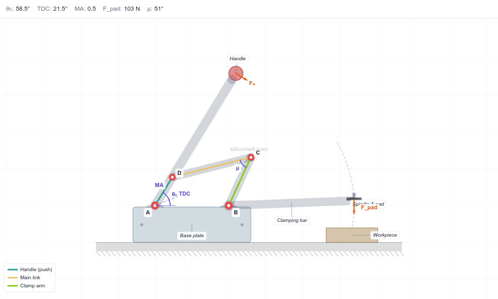
Calculating Mechanical Advantage
Mechanical Advantage (MA) = Output Force / Input Force
For a toggle clamp:
Where θ is the angle between main link and clamp arm.
As θ approaches 90°, MA maximizes.
As θ approaches 180° (dead center), MA approaches infinity.
Challenges for Further Practice
Add adjustable clamping force - threaded adjustment screw
Design a hold-down clamp variant (vertical clamp arm)
Add a release lever for quick-release
Create a spring return mechanism
Design mounting holes for T-slot table mounting
Add rubber clamping pads (different material)
Common Issues and Solutions
“Mechanism doesn’t lock”
Cause: Not achieving over-center (angle < 180°)
Solution: Increase OverCenterAngle parameter
Fix: Adjust pivot positions to allow greater angle
“Too hard to close”
Cause: Over-center angle too large, or friction
Solution: Reduce OverCenterAngle closer to 180°
Fix: Check pin clearances
“Handle hits clamp arm”
Cause: Insufficient clearance
Solution: Offset handle vertically (different Z position) or adjust geometry
Fix: Use clearance-aware design, check interference in assembly
“Cannot achieve full motion range”
Cause: Link lengths incompatible with desired positions
Solution: Recalculate link lengths using kinematic equations
Fix: Adjust MainLinkLength or ClampArmLength
Next Steps
In the next lesson on Pantograph Mechanism , we’ll explore:
Ratio-based motion scaling
Similar triangle geometry
Copying and tracing mechanisms
Expression-driven parametric relationships
Precision motion duplication
Comments