🎓 Grashof's Theorem
The behavior depends critically on link length relationships.
Where:
- S = shortest link length
- L = longest link length
- P, Q = intermediate link lengths
A single rotating shaft can drive a windshield wiper, a rocking sprinkler, or a walking robot leg, all with the same basic mechanism: four rigid links and four pin joints. The difference between a smooth, reliable motion and a mechanism that locks up mid-cycle comes down to link length ratios, which is exactly what Grashof’s Theorem predicts. In this lesson you will design a four-bar linkage in FreeCAD using master sketch techniques and expression-driven dimensions, then verify Grashof’s condition to guarantee full rotation of the input crank. #FreeCAD #FourBarLinkage #GrashofTheorem #MasterSketch
By the end of this lesson, you will be able to:
The four-bar linkage is one of the simplest yet most versatile planar mechanisms in mechanical engineering. It forms the backbone of countless mechanical systems, from vehicle suspensions to robotic arms, and understanding its design is fundamental to mechanism synthesis.
The four-bar linkage appears in countless engineering applications:
Design Challenge: Given four rigid links connected by revolute joints with one link fixed, how do we create controlled motion transformation with predictable path characteristics and full rotation capability?
A four-bar linkage consists of four elements working together:
1. Ground Link (Link 1)
2. Input Link/Crank (Link 2)
3. Coupler (Link 3)
4. Output Link/Follower (Link 4)
🎓 Grashof's Theorem
The behavior depends critically on link length relationships.
Where:
If the inequality holds (Grashof linkage):
Which link is ground determines behavior:
If inequality doesn’t hold (Non-Grashof):
For this lesson, we’ll use:
| Link | Length | Role |
|---|---|---|
| Link 1 (ground) | 100 mm | Fixed base |
| Link 2 (crank) | 40 mm | Input rotator |
| Link 3 (coupler) | 80 mm | Connector |
| Link 4 (follower) | 70 mm | Output oscillator |
Grashof Check:
By completing this lesson, you’ll create:
Master Sketch Layout
One kinematic sketch controlling all four parts simultaneously
Parametric Linkage
Four interacting parts driven by spreadsheet parameters
Working Assembly
Pin-jointed mechanism demonstrating Grashof’s Theorem
Technical Drawing
Professional documentation for manufacturing linkage plates
We’ll use a master sketch approach: defining the complete kinematic layout once, then referencing it from all parts. This is how professionals design mechanisms where geometric relationships between parts are more critical than individual part dimensions.
🎯 Master Sketch Philosophy
We’ll control the entire four-bar mechanism with one master sketch plus four length parameters:
Link1 = 100 mm Link2 = 40 mm Link3 = 80 mm Link4 = 70 mm
Change the master sketch → all parts update automatically!
This is the power of kinematic-first parametric design.
Create Spreadsheet (parameter table)
Create Master Sketch (kinematic layout)
Create Link 1 - Ground (reference master)
Create Link 2 - Crank (reference master)
Create Link 3 - Coupler (reference master)
Create Link 4 - Follower (reference master)
Assemble with pin joints
Create technical drawing
Test Grashof configurations
Create a new document
File → New (or Ctrl+N)Save it as FourBarLinkage.FCStd
Switch to Part Design workbench
Use the workbench dropdown at top
Insert a spreadsheet
Insert → SpreadsheetA “Spreadsheet” object appears in the left tree
Double-click to open the spreadsheet
Click on “Spreadsheet” in the tree
In the spreadsheet, create this table:
| Cell | Value | Meaning |
|---|---|---|
| A1 | Parameter | Header |
| B1 | Value | Header |
| C1 | Unit | Header |
| A2 | Link1 | Ground link length |
| B2 | 100 | Numeric value |
| C2 | mm | Unit (documentation) |
| A3 | Link2 | Crank length |
| B3 | 40 | Numeric value |
| C3 | mm | Unit |
| A4 | Link3 | Coupler length |
| B4 | 80 | Numeric value |
| C4 | mm | Unit |
| A5 | Link4 | Follower length |
| B5 | 70 | Numeric value |
| C5 | mm | Unit |
| A6 | LinkWidth | Link plate width |
| B6 | 20 | Numeric value |
| C6 | mm | Unit |
| A7 | LinkThickness | Link plate thickness |
| B7 | 8 | Numeric value |
| C7 | mm | Unit |
| A8 | PinRadius | Pin hole radius |
| B8 | 4 | Numeric value |
| C8 | mm | Unit |
Why Aliases?
Aliases let you reference cells by name instead of “B2”, making formulas readable and meaningful.
Create aliases:
Click cell B2
Right-click → Properties
In “Alias” field, type: Link1
Click OK
Repeat for all parameter cells (B2 through B8):
Link1Link2Link3Link4LinkWidthLinkThicknessPinRadiusNow you can use Spreadsheet.Link1 anywhere in your model!
Close the spreadsheet when done (click the Close button).
Your parameter foundation is ready!
🎯 Master Sketch Concept
A master sketch defines the kinematic layout: where joints are located and how links connect. All parts reference this sketch geometry as their positional truth.
Key Benefits:
Ensure you’re in Part Design workbench
Create new sketch on XY_Plane
This sketch won’t belong to a body; it’s standalone reference geometry!
Draw a horizontal line:
Line tool (press L)
Click at origin (0, 0)
Move horizontally to the right
Click to place endpoint
Press Escape
Make it horizontal:
Fix the start point:
Dimension the link:
Spreadsheet.Link1Draw a line from point A:
Line tool (L)
Start at the left endpoint of Link 1 (point A)
Draw at an angle upward-right
Click to place endpoint
Press Escape
Constrain the link:
Dimension the length:
Spreadsheet.Link2This is the crank, connecting joints A and C.
Draw a line from point B:
Line tool (L)
Start at right endpoint of Link 1 (point B)
Draw upward at an angle
Click to place endpoint
Press Escape
Constrain:
Spreadsheet.Link4This is the follower, connecting joints B and D.
Draw a line connecting the free ends:
Line tool (L)
Start at free end of Link 2 (point C)
End at free end of Link 4 (point D)
Press Escape
Constrain:
Spreadsheet.Link3Make sketch reference-only:
Select all four lines
Toggle construction geometry
🎯 Why Construction Geometry?
Construction geometry is reference only:
This is the key to master sketch workflows!
Check and close:
Check constraints:
The sketch should be fully constrained. Verify:
Optional: Add angle dimension
If under-constrained, add angle to Link 2:
30 degreesClose the sketch
Click Close button in toolbar
⚙️ Link 1 Requirements
Link 1 is a rectangular plate with:
Create a Body
Link1_GroundCreate a Sketch
Reference master sketch geometry:
External geometry tool (press E)
Click the master sketch in the tree
Select joint A endpoint (origin)
Select joint B endpoint (right end of Link 1)
Press Escape
Draw circles at both joints:
Circle tool (C)
Draw circle centered at origin (joint A)
Press Escape
Circle tool again
Draw circle at joint B reference point
Press Escape
Constrain both circles:
Dimension the holes:
Spreadsheet.PinRadiusCreate the connecting plate:
Rectangle tool
Draw rectangle connecting the two circles
Press Escape
Symmetric constraint:
Dimension width:
Spreadsheet.LinkWidthComplete the sketch:
Verify fully constrained
Check solver messages panel
Close sketch
Click Close button
Pad the link
Spreadsheet.LinkThicknessCreate Body → Rename to Link2_Crank
Create Sketch on XY_Plane
Reference Master Sketch Geometry:
Draw the Link:
Spreadsheet.PinRadiusSpreadsheet.PinRadiusSpreadsheet.LinkWidthVerify fully constrained and Close sketch
Pad:
Spreadsheet.LinkThicknessLink 2 complete!
Body: Create and rename to Link3_Coupler
Sketch on XY_Plane
Reference points C and D from master sketch (External geometry tool)
Draw the link:
Pad with thickness parameter
Link 3 complete!
Body: Create and rename to Link4_Follower
Sketch on XY_Plane
Reference points B and D from master sketch
Draw the link:
Pad with thickness parameter
Assembly is where your individual linkage plates come together as a functioning mechanism. By applying pin joint constraints, you’ll see Grashof’s Theorem in action as the crank rotates and the follower oscillates!
🎯 Constraint Plan
All joints use Axial Align constraints to allow rotation!
Switch to Assembly workbench
Use workbench dropdown
Create new assembly
Assembly → Create Assembly
Add all four parts
Drag from tree or use “Add Part” button:
Select Link1_Ground in assembly tree
Click Fixed constraint button
Link 1 is now locked in place (ground reference)
Apply Axial Align constraints at all four joints:
Joint A (Link 1 - Link 2):
Joint B (Link 1 - Link 4):
Joint C (Link 2 - Link 3):
Joint D (Link 3 - Link 4):
Test the mechanism:
Drag Link 2 (the crank) in the assembly view
Observe motion:
Troubleshooting:
Switch to TechDraw workbench
Create a page:
Add views:
Add dimensions:
Title block:
Export:
This is the moment of truth! A truly parametric mechanism updates correctly when you change parameters. Let’s verify your design is intelligent, test Grashof’s Theorem, and explore different linkage configurations.
Open Spreadsheet
Double-click Spreadsheet in tree
Change Link2 to 50mm
50Recompute
Press Ctrl+R or click Recompute button
Observe changes:
✅ Success! Your mechanism is parametric!
Try these link length configurations:
Configuration 1: Crank-Rocker (original)
Link1 = 100, Link2 = 40, Link3 = 80, Link4 = 70
Configuration 2: Double-Rocker
Link1 = 40, Link2 = 100, Link3 = 80, Link4 = 70
Configuration 3: Non-Grashof
Link1 = 100, Link2 = 20, Link3 = 80, Link4 = 70
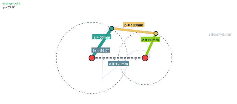
Push the limits:
Set Link2 = 60, Link3 = 120
Recompute
Entire mechanism scales up!
Try different ratios:
Everything should update cleanly!
Congratulations! By completing this lesson, you have:
✅ Master Sketch Technique
Created kinematic layout controlling multiple parts
✅ Construction Geometry
Used reference-only geometry for design intent
✅ External References
Referenced geometry across multiple sketches
✅ Grashof's Theorem
Applied link length theory in practice
✅ Pin-Jointed Assembly
Assembled four-link mechanism with motion
✅ Parametric Mechanism
Built intelligent, reconfigurable design
Most importantly: You’ve designed a complete four-bar linkage mechanism using professional kinematic-first methodology!
Use this checklist to verify your design:
Ready for more? Try these enhancements:
Add fillets
Use Fillet tool to round sharp edges (2mm radius)
Add more parameters
Control all dimensions via spreadsheet (currently some are hardcoded)
Create drawings for all four links
Generate complete documentation set
Design connecting pins
Create separate pin parts for each joint
Add a coupler point
Place a marker on Link 3, observe its path
Create assembly drawing
Show full mechanism with dimensions
Plot coupler curves
Use Python to trace coupler point paths
Motion study
Create animation showing one complete cycle
Design straight-line mechanism
Find link ratios that create approximate straight-line motion (Chebyshev linkage)
Add velocity analysis
Calculate and plot link angular velocities
“Parts don’t align in assembly”
“Mechanism is locked/won’t move”
“Master sketch is under-constrained”
“External geometry not updating”
“Parts don’t update with spreadsheet”
In Lesson 3: Scissor Lift Mechanism, you’ll explore:
Repeating Linkages
Create arrays of identical four-bar units
Symmetric Design
Mirror constraints and balanced mechanisms
Motion Amplification
How cascading linkages multiply displacement
Load Path Analysis
Understanding forces in pin-jointed structures
Each lesson builds on the parametric CAD fundamentals while introducing new mechanism types and advanced design techniques!
Comments