A single hydraulic cylinder gives you limited stroke, typically a few hundred millimeters. A scissor lift multiplies that stroke through cascaded X-shaped links: three stages can turn 100 mm of cylinder travel into 600 mm of vertical rise while keeping the footprint compact and the load centered. The challenge is that each additional stage changes the geometry of every other stage, making manual dimensioning tedious and error-prone. In this lesson you will design a scissor lift in FreeCAD where a single parameter controls the number of stages and every link updates automatically. #FreeCAD #ScissorLift #VerticalMotion #RepeatingGeometry
Learning Objectives
By the end of this lesson, you will be able to:
Design symmetrical mechanisms with repeating geometry
Create parametric links with multiple pin connections
Control stage count and dimensions via spreadsheet parameters
Assemble pin-jointed collapsible structures
Manage multiple instances of the same parametric part
Engineering Context: Why This Mechanism Matters
Scissor lift mechanisms provide vertical motion through a compact, stable structure using multiple interconnected linkages. They’re fundamental to many height-adjustment and material handling applications, converting small horizontal input motion into amplified vertical displacement.
Real-World Applications
The scissor lift appears everywhere in engineering:
The Engineering Problem
Design Challenge: Given limited horizontal space, how do we achieve significant vertical lifting with a stable, compact mechanism that stores efficiently when collapsed?
Mechanism Fundamentals
Components and Motion
A scissor mechanism consists of crossed links working in harmony:
The scissor lift uses the same arm design multiple times. This repeating geometry pattern is key to scalable parametric design: design once, use everywhere, control centrally.
Our Design Approach
🎯 Repeating Geometry Philosophy
We’ll control the entire scissor lift with parametric design:
ArmLength = 200 mm
ArmWidth = 30 mm
StageCount = 2 (for documentation)
Design ONE perfect arm → Use it four times (for 2-stage lift)!
This is industrial-strength parametric methodology.
Draw a rectangle that encompasses all three circles
Should extend past the leftmost and rightmost circles
Press Escape
Don’t worry about exact positioning yet. Constraints will fix it!
Center the rectangle about centerline:
Click Symmetric constraint tool
Click the top edge of the rectangle
Click the bottom edge of the rectangle
Click the horizontal centerline (construction line)
Press Escape
The rectangle is now perfectly centered vertically!
Set the parametric width:
Distance constraint tool
Click the top edge of rectangle
Click the bottom edge of rectangle
ƒx button
Type: Spreadsheet.ArmWidth
Enter
Arm width is now 30mm and parametric!
The rectangle length is automatically constrained!
Because the rectangle corners will be coincident with or near the end hole centers (which are already positioned at the centerline endpoints), the rectangle length is implicitly defined.
If the solver shows degrees of freedom, add:
Coincident: Rectangle left edge → passes through left hole center
Coincident: Rectangle right edge → passes through right hole center
Or simply ensure the rectangle extends to the endpoints.
Finalizing the Sketch
Check the solver
Look at “Solver Messages” panel:
Should say “Fully constrained”
If it says “X degrees of freedom”, review constraints
Assembly is where your individual parts come together as a functioning mechanism. The scissor lift assembly uses the same arm part twice in a crossed configuration, demonstrating how parametric parts can be reused in different orientations.
Use workbench dropdown (Assembly4 or A2plus recommended)
Create new assembly
Assembly → Create Assembly
Add parts
You need to add:
BasePlatform (once)
ScissorArm (twice - same part, two instances!)
TopPlatform (once)
Use “Add Part” or drag from tree, adding ScissorArm twice
Select BasePlatform in assembly tree
Click Fixed constraint button
Base is now locked in place (ground link)
Position the left-rising arm:
Select the left end hole axis of the first ScissorArm
Select the left pin hole axis of the BasePlatform
Click Axial Align constraint
The first arm’s left end is now connected to the base!
Position the right-rising arm:
Select the left end hole axis of the second ScissorArm
Select the right pin hole axis of the BasePlatform
Click Axial Align constraint
The second arm’s left end connects to the right side of the base!
This is the critical scissor pivot!
Select the center hole axis of first ScissorArm
Select the center hole axis of second ScissorArm
Click Axial Align constraint
The arms now cross and can pivot relative to each other!
Connect to the top platform:
First arm’s right end hole → TopPlatform right pin hole
Axial Align constraint
Second arm’s right end hole → TopPlatform left pin hole
Axial Align constraint
The mechanism is now complete!
Test the scissor action:
Try dragging the top platform or an arm in the assembly view:
Arms should rotate about their pivots
Center crossing should move
Top platform should rise and fall!
Motion should be smooth and coordinated
Part 7: Technical Drawing
Creating Professional Documentation
Switch to TechDraw workbench
Create a page:
Insert Page
Choose template: A3_Landscape (assembly drawings need space)
Add assembly views:
Insert View → Select entire assembly
Create Front view (collapsed position)
Create Side view
Position views by dragging
Add detail view of arm:
Insert View → Select ScissorArm body
Show dimensions and hole positions
Use Dimension tools: Horizontal, Vertical, Radius
Add parts list:
Create a table showing:
Part
Qty
Material
Scissor Arm
2
Steel
Base Platform
1
Steel
Top Platform
1
Steel
Pin (8mm dia)
5
Steel
Title block:
Double-click text fields
Enter: Part name, material, scale, your name, date
Export:
Right-click page → Export as PDF
You now have professional engineering documentation!
Part 8: Testing Parametric Control
This is where parametric design proves its worth! A truly parametric model updates correctly when you change parameters. Let’s verify your scissor lift is intelligent and responsive to design changes.
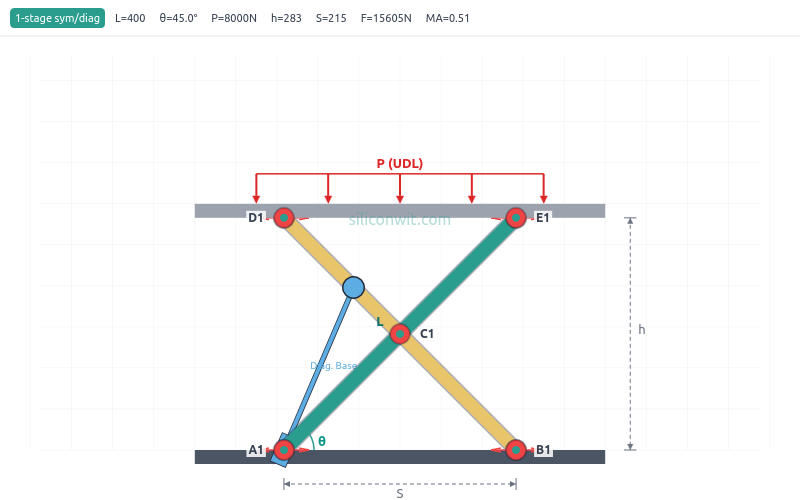
Simulate it: Use the Scissor Lift Mechanism Simulator to analyze the kinematics and forces of the mechanism you just built. Adjust link length, number of stages, actuator type, and load in real time to see height, force, power, and stability plots.
Run experiments: Follow the Scissor Lift Experiments for nine structured lab exercises with Python data analysis.
Read more: See the 2D Mechanisms Analyzer for a full overview of the simulator’s capabilities and downloadable resources.
In Lesson 4: Toggle Clamp Mechanism, you’ll explore:
Over-Center Locking
Mechanisms that lock in position geometrically
Force Amplification
Mechanical advantage through linkage geometry
Motion Limits
Constraining range and adding hard stops
Contact Geometry
Designing cam surfaces and follower paths
Each lesson builds on parametric fundamentals while introducing new mechanisms and CAD techniques!
Comments