Motion Programming
The cam surface directly determines follower motion. As the cam rotates, its profile shape pushes the follower through a prescribed path.
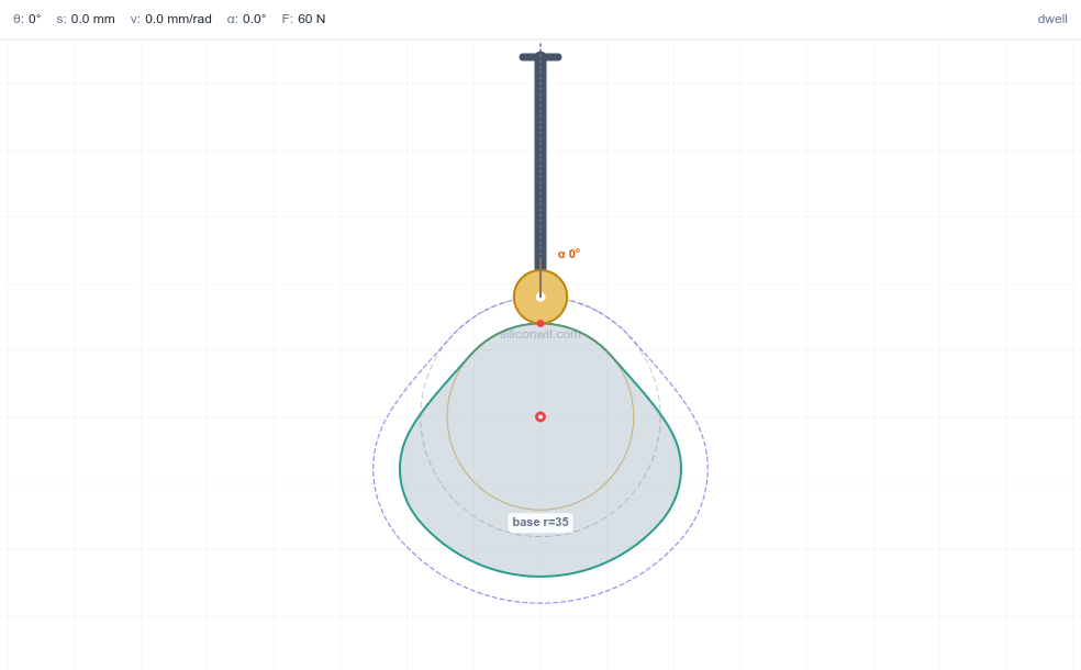
Gears and linkages convert one type of motion into another, but they cannot produce an arbitrary motion profile. When you need a valve to open slowly, dwell at the top, and snap shut, or a pick-and-place arm to follow a specific acceleration curve, you need a cam. The cam’s profile is the motion program carved into metal, and getting that profile wrong means the follower jams, bounces, or wears prematurely. In this lesson you will design a cam and follower mechanism in FreeCAD with parametric control over the rise, dwell, and return segments. #FreeCAD #CamDesign #FollowerMotion #ProgrammedMotion
By the end of this lesson, you will be able to:
Cam and follower mechanisms convert continuous rotary motion into precisely controlled reciprocating or oscillating motion. They’re fundamental to timing and sequencing in mechanical systems, with the cam profile acting as a geometric program that defines the follower’s motion.

Cam and follower mechanisms power critical timing and sequencing operations across industries:
Design Challenge: Given continuous rotary input motion, how do we create a specific, repeatable output motion profile with precise timing, smooth acceleration, and reliable contact?
Key Concept: The cam profile = motion program encoded as geometry
Motion Programming
The cam surface directly determines follower motion. As the cam rotates, its profile shape pushes the follower through a prescribed path.
Design Flexibility
Change the cam profile geometry, change the motion. One rotating input creates unlimited possible output motions.
A cam and follower system consists of three essential elements:
1. Cam: Rotating Driver
2. Follower: Moving Output
3. Frame: Fixed Reference
⚙️ Follower Configurations
Roller Follower (Most Common)
Flat-Faced Follower
Knife-Edge Follower
Standard Cam Cycle:
A complete 360° rotation typically includes four phases:
Rise: Outward Motion
Dwell: High Position
Return: Inward Motion
Dwell: Low Position
Base Circle Radius (R_b)
Lift (L)
Prime Circle Radius (R_p)
Rise Angle
Dwell Angles
Return Angle
Simple Harmonic Motion
Where:
Cycloidal Motion
Polynomial Motion
By completing this lesson, you’ll create:
Custom Cam Profile
Parametrically controlled cam with 120° rise, 60° dwell, 120° return, 60° dwell
Roller Follower Assembly
Complete follower system with roller, stem, and guide
Motion Documentation
Technical drawings showing motion zones and displacement diagrams
Parametric Control
Adjust lift, base radius, or angles: entire mechanism updates automatically
Launch FreeCAD
Ensure you’re using version 0.21 or later
Create new document
File → New (Ctrl+N)
Save immediately
Save as CamFollower.FCStd in your project folder
Good Practice - Save early, save often!
For this lesson, you’ll use:
Part Design
Sketcher
Spreadsheet
Assembly
TechDraw
Essential Navigation Controls:
| Action | Control |
|---|---|
| Rotate view | Middle mouse button + drag |
| Pan view | Shift + Middle mouse button + drag |
| Zoom | Mouse wheel scroll |
| Fit all | Press “V” then “F” |
| View front | Press “1” on numpad |
| View top | Press “7” on numpad |
Practice Now!
Cam design requires thinking in terms of motion profiles first, then translating those profiles into geometry. The cam surface is literally a physical encoding of the desired motion: every point on the profile corresponds to a specific follower position at a specific rotation angle.
🎯 Cam Cycle Specification
360° Complete Cycle:
This creates smooth, repeatable motion with predictable timing.
We’ll control the entire mechanism with these key parameters:
BaseCircleRadius = 40 mmLift = 20 mmRollerRadius = 10 mmCamThickness = 15 mmShaftDiameter = 20 mmSwitch to Part Design workbench
Use the workbench dropdown at top
Insert a spreadsheet
Insert → Spreadsheet
A “Spreadsheet” object appears in the left tree
Double-click to open the spreadsheet
Click on “Spreadsheet” in the tree
In the spreadsheet, create this parameter table:
| Cell | Value | Meaning |
|---|---|---|
| A1 | Parameter | Header |
| B1 | Value | Header |
| C1 | Unit | Header |
| A2 | BaseCircleRadius | Parameter name |
| B2 | 40 | Numeric value |
| C2 | mm | Unit (documentation) |
| A3 | Lift | Parameter name |
| B3 | 20 | Numeric value |
| C3 | mm | Unit |
| A4 | PrimeCircleRadius | Parameter name |
| B4 | =B2+B3 | Formula |
| C4 | mm | Unit |
| A5 | RollerRadius | Parameter name |
| B5 | 10 | Numeric value |
| C5 | mm | Unit |
| A6 | CamThickness | Parameter name |
| B6 | 15 | Numeric value |
| C6 | mm | Unit |
| A7 | ShaftDiameter | Parameter name |
| B7 | 20 | Numeric value |
| C7 | mm | Unit |
| A8 | ShaftRadius | Parameter name |
| B8 | =B7/2 | Formula |
| C8 | mm | Unit |
| A9 | RiseAngle | Parameter name |
| B9 | 120 | Numeric value |
| C9 | deg | Unit |
| A10 | DwellAngle1 | Parameter name |
| B10 | 60 | Numeric value |
| C10 | deg | Unit |
| A11 | ReturnAngle | Parameter name |
| B11 | 120 | Numeric value |
| C11 | deg | Unit |
| A12 | DwellAngle2 | Parameter name |
| B12 | 60 | Numeric value |
| C12 | deg | Unit |
Why Aliases?
Aliases let you reference cells by descriptive names instead of cell addresses like “B2”, making formulas readable and maintainable.
Create aliases for all parameter values:
Click cell B2
Right-click → Properties
In “Alias” field, type: BaseCircleRadius
Click OK
Repeat for each parameter value in column B:
LiftPrimeCircleRadiusRollerRadiusCamThicknessShaftDiameterShaftRadiusRiseAngleDwellAngle1ReturnAngleDwellAngle2Now you can use Spreadsheet.BaseCircleRadius anywhere in your model!
Notice the formulas in B4 and B8:
PrimeCircleRadius = BaseCircleRadius + Lift
ShaftRadius = ShaftDiameter / 2
Close the spreadsheet when done (click the Close button).
Your parametric foundation is ready!
The cam profile must be designed relative to the follower position. For a roller follower, we actually design the pitch curve: the path traced by the roller center. Then the actual cam surface is offset inward by the roller radius. This ensures the roller maintains proper contact throughout the cycle.
Simple Harmonic Motion Rise:
For smooth acceleration during rise, we use simple harmonic motion:
Where:
Cam Radius at Angle θ:
Where:
Key Points for 120° Rise:
| Angle | Displacement | Radius |
|---|---|---|
| 0° | 0 mm | 40 mm |
| 30° | 2.68 mm | 42.68 mm |
| 60° | 10 mm | 50 mm |
| 90° | 17.32 mm | 57.32 mm |
| 120° | 20 mm | 60 mm |
Two Approaches:
Option A: B-Spline Through Calculated Points (Accurate)
Option B: Circular Arc Approximation (Simplified)
Cam Profile Construction:
Base Circle:
Rise Section (0° to 120°):
High Dwell (120° to 180°):
Return Section (180° to 300°):
Low Dwell (300° to 360°):
Shaft Hole:
Create a Body
CamCreate a Sketch
You’re now in Sketcher workbench (automatic switch)
Draw the base circle
Constrain the radius
Spreadsheet.BaseCircleRadiusBase circle is now parametrically controlled!
We’ll use construction geometry to establish angular positions:
Draw horizontal reference line
Make it construction geometry
Constrain it horizontal
Set the length
70 mm (extends beyond prime circle)This horizontal line at 0° is our angular reference.
Simplified approach using a single arc:
Draw arc from base to prime circle
Constrain start point
Constrain end point angle
Constrain end point radius
Spreadsheet.PrimeCircleRadiusThe rise section is now constrained!
For more accurate harmonic motion (optional):
Calculate and place points
Using the table from earlier:
Use Point tool
Place points at each calculated position
Constrain each point
Connect with B-spline
This creates a smooth curve matching the harmonic motion law exactly.
Draw arc at prime circle radius
Constrain the arc
Spreadsheet.PrimeCircleRadiusHigh dwell maintains follower at maximum lift while cam rotates 60°.
Easiest method: Mirror the rise section
Create symmetry axis
Select rise geometry
Apply symmetry constraint
Position correctly
The mirrored section should span 180° to 300°
Alternative: Draw return section manually
Draw return arc
Constrain endpoints
Constrain radii
Spreadsheet.PrimeCircleRadiusSpreadsheet.BaseCircleRadiusDraw arc at base circle radius
Constrain the arc
Spreadsheet.BaseCircleRadiusThe profile is now a complete closed curve!
Draw center hole
Constrain the hole
Spreadsheet.ShaftRadiusCheck the solver
Look at “Solver Messages” panel:
Visual verification
The cam profile should show:
Close the sketch
Click the Close button in the toolbar
Select the cam sketch
Click on the sketch in the tree (under Cam body)
Apply Pad operation
Spreadsheet.CamThicknessView your cam
Your parametric cam is complete!
🔧 Follower Assembly Components
The follower system consists of three parts:
Roller
Follower Stem
Guide Mount (part of frame)
Create new Body
RollerCreate Sketch on XZ_Plane
Why XZ? The follower moves vertically (Z-axis) and we’ll revolve around a horizontal axis
Draw roller profile
Constrain the circle
70 mmSpreadsheet.RollerRadiusCheck and close sketch
📦 Revolve Operation
Revolve creates 3D solids by rotating a 2D profile around an axis, like a lathe operation.
Perfect for:
Select the roller sketch in the tree
Click Revolve tool in Part Design toolbar
In the Revolve panel:
360° (full rotation)Click OK
You now have a cylindrical roller!
Create new Body
FollowerStemCreate Sketch on XZ_Plane
Draw stem profile
Constrain the rectangle
30 mm15 mm80 mmClose sketch
Pad the stem
10 mm (creates rectangular bar in Y direction)Follower stem complete!
For this lesson, we’ll position roller and stem together in assembly without a physical pin connection. This keeps the focus on cam motion.
For more realism:
Create another Body: RollerPin
Sketch a circle (pin cross-section) on appropriate plane
Revolve to create cylindrical pin
Position to connect roller to stem in assembly
The frame provides:
Create new Body
FrameCreate Sketch on XY_Plane
Draw base plate
Rectangle tool
Width: 150mm
Height: 100mm
Centered at origin
Symmetric constraints: Center rectangle about both X and Y axes
Distance constraints: Width = 150 mm, Height = 100 mm
Add cam shaft hole
Spreadsheet.ShaftRadius + 0.5 (add clearance)Note: You can type the formula directly or use a fixed value like 10.5 mm
Add follower guide slot
Draw two vertical parallel lines for guide rails
Position: X = ±10 mm (creates 20mm wide slot for 15mm stem + clearance)
Height: 100mm (full range of motion)
Symmetric: Left and right lines about Y-axis
Distance between: 20 mm
Close sketch
Pad the frame
20 mmFrame complete!
Assembly transforms individual parts into a functioning mechanism. For the cam and follower, we must establish rotational motion for the cam while constraining the follower to pure vertical translation. The roller maintains contact with the cam surface through careful positioning.
🎯 Assembly Constraints Plan
Switch to Assembly workbench
Use workbench dropdown (may be labeled “Assembly 3” or “Assembly 4” depending on version)
Create new assembly
Assembly → Create Assembly
An assembly container appears in the tree
Add parts
Drag parts from tree into assembly or use “Add Part” button:
Select Frame in assembly tree
Apply Fixed constraint
Click Fixed or Lock constraint button
Frame is now locked in place
This serves as the ground reference for all motion
Allow cam to rotate about shaft:
Select cam shaft hole axis
Click on the circular edge or use the References panel
Select frame shaft hole axis
Apply Axial Align constraint
This aligns the axes and allows rotation about that axis
Test: Try rotating the cam manually in the assembly view - it should spin about the Z-axis!
Constrain follower to vertical motion only:
Select follower stem body
Select frame guide surfaces
You may need to select the parallel guide rails or frame top surface
Apply constraints for vertical sliding:
The exact constraint type depends on your Assembly workbench version
Goal: Follower can slide up and down (Z-axis) but cannot move sideways or rotate
Position roller at bottom of stem:
Select roller and follower stem
Apply constraints:
Adjust height so roller just touches cam base circle
Manual motion verification:
Rotate cam slowly in the assembly
Grab the cam and rotate it incrementally
Manually adjust follower height to maintain roller contact with cam
As cam rotates through rise, move follower up During dwell, keep follower stationary During return, move follower down
Observe the cycle:
Cam mechanism drawings require more than standard part views. They must clearly communicate the motion profile, angular zones, and follower displacement. Essentially, they document the programmed motion encoded in the cam geometry.
Switch to TechDraw workbench
Create a page
Add cam top view
This shows the cam profile clearly
Add cam section view
Add angular dimension tool
Select angular dimension from toolbar
Dimension each motion zone
Add text annotations
Use Text tool to label:
RISE (120°)
DWELL (60°)
RETURN (120°)
DWELL (60°)
Add critical dimensions:
Base circle radius
Radial dimension: 40mm
Prime circle radius
Radial dimension: 60mm
Lift
Linear dimension showing 20mm difference
Shaft hole
Diameter dimension: 20mm
Cam thickness
Side view dimension: 15mm
📊 Follower Displacement Diagram
A displacement diagram is essential for cam documentation. It’s a graph showing follower position vs. cam rotation angle.
Axes:
Profile:
Create sketch on drawing page
Use TechDraw → Insert Sketch
Draw axes
Plot the profile
Label axes and zones
For more accurate diagram:
Use the motion law formulas to calculate displacement at multiple angles, then plot:
| Angle | Displacement |
|---|---|
| 0° | 0 mm |
| 30° | 2.68 mm |
| 60° | 10 mm |
| 90° | 17.32 mm |
| 120° | 20 mm |
| 180° | 20 mm |
| 210° | 17.32 mm |
| 240° | 10 mm |
| 270° | 2.68 mm |
| 300° | 0 mm |
| 360° | 0 mm |
Plot these points and connect smoothly.
Complete title block
Add notes
NOTES:1. Motion profile: Simple harmonic rise and return2. Break all sharp edges 0.5mm3. Surface finish: Ra 1.6 on cam profile4. Heat treat to Rc 50-55 (if steel)Export
The true test of parametric design: change a parameter, watch the entire mechanism update correctly. This is where hours of careful constraint work pay off with instant design iterations.
Open Spreadsheet
Double-click Spreadsheet in tree
Change Lift parameter
30Recompute
Press Ctrl+R or click Recompute button
Observe changes:
✅ Success! Your lift is parametric!
Change BaseCircleRadius
50Recompute (Ctrl+R)
Verify:
✅ Your cam scales parametrically!
Change CamThickness
25Recompute
Verify:
✅ Thickness updates correctly!
Try these configurations:
| Configuration | BaseCircleRadius | Lift | Character |
|---|---|---|---|
| Compact | 30 | 15 | Small, tight motion |
| Standard | 40 | 20 | Balanced (original) |
| Extended | 50 | 30 | Large stroke, smooth |
| Extreme | 60 | 40 | Very large motion |
Watch how the cam profile adapts!
Congratulations! By completing this lesson, you have:
✅ Designed Cam Profiles
Curve-based profiles with motion laws
✅ Applied Polar Geometry
Angular constraints and radial dimensions
✅ Created Contact Systems
Cam-follower contact motion
✅ Used Revolve Operation
Rotationally symmetric parts
✅ Modeled Complex Motion
Rise-dwell-return cycles
✅ Documented Motion
Displacement diagrams and annotated zones
Most importantly: You’ve designed a motion-programming mechanism: geometry that directly controls motion characteristics!
Use this checklist to verify your cam design:
Ready for more? Try these enhancements:
Add return spring
Model a compression spring that keeps follower in contact with cam
Create cam with different dwell timing
Try 90° rise, 90° dwell, 90° return, 90° dwell
Add more parameters
Control rise angle, dwell angles via spreadsheet
Design cycloidal motion cam
Use cycloidal equations for smoother acceleration
Create flat-faced follower
Replace roller with flat contact surface
Add manufacturing features
Keyway in shaft hole, mounting bolt holes
Calculate and plot velocity/acceleration
Derive velocity and acceleration from displacement curve
Design conjugate cam
Two cams on same shaft for balanced forces
Create positive-drive cam
Groove cam that drives follower in both directions
FEA stress analysis
Analyze contact stresses using FEM workbench
“Cam profile has sharp corners”
“Profile doesn’t close properly”
“Follower motion is jerky”
“Roller doesn’t maintain contact”
“Cam profile breaks when changing parameters”
“Cannot create B-spline smoothly”
In the next lesson on Geneva Mechanism, you’ll explore:
Intermittent Motion
Precise indexing and locking mechanisms
Polar Patterns
Symmetrically arranged features
Locking Geometry
Self-locking designs for safety
Angular Precision
Exact angle control and repeatability
Each lesson builds your parametric CAD mastery while exploring fundamental mechanisms!
Comments