Skip to content

Lesson 2.6: Principal Stresses and Failure Criteria Analysis


🎓 Mechanics of Materials I & II: Advanced Stress Analysis Conclusion

This final unit represents the culmination of our systems-based solid mechanics journey. We conclude with the most sophisticated stress analysis techniques - principal stress determination and failure prediction under complex loading states. These methods form the foundation for safe, reliable mechatronic system design.


🎯 Learning Objectives

By the end of this lesson, you will be able to:

  1. Construct Mohr’s circle for any 2D stress state in mechatronic components
  2. Determine principal stresses and maximum shear stresses graphically and analytically
  3. Apply appropriate failure theories for different materials and loading conditions
  4. Predict failure modes in complex mechatronic joint designs

🔧 Real-World System Problem: Universal Joint in Robotic Drive System

Universal joints in robotic drive trains experience complex 3D stress states from transmitted torque, bending moments, and contact forces. Understanding principal stress distributions and applying appropriate failure criteria is essential for preventing catastrophic failures in critical robotic applications.

System Description

Robotic Universal Joint Components:

  • Cross Pin (transmits torque between intersecting shafts)
  • Bearing Races (allow rotation while constraining radial motion)
  • Fork Arms (connect to input and output shafts)
  • Needle Bearings (reduce friction in oscillating motion)
  • Sealing System (protects against contamination)

The Complex Stress Challenge

During robotic operation, the universal joint pin experiences:

Engineering Question: How do we determine the critical stress state in a universal joint pin that experiences 500 N·m torque, 200 N·m bending moment, and bearing contact forces, and predict which failure mode is most likely to occur?

Why Principal Stress Analysis Matters

Consequences of Inadequate Stress Analysis:

  • Unexpected joint failure during critical operations
  • Catastrophic system shutdown from drive train failure
  • Safety hazards in human-robot collaborative environments
  • Expensive repairs and extended downtime
  • Loss of system reliability and customer confidence

Benefits of Comprehensive Stress Analysis:

  • Accurate failure prediction under complex loading
  • Optimized joint geometry for maximum reliability
  • Material selection based on actual stress states
  • Preventive maintenance scheduling based on stress analysis

📚 Fundamental Theory: Principal Stress Analysis

The General Stress State

At any point in a stressed body, the stress state can be described by:

2D Stress Components:

  • Normal stresses: σ_x, σ_y
  • Shear stress: τ_xy (= τ_yx)

3D Stress Components:

  • Normal stresses: σ_x, σ_y, σ_z
  • Shear stresses: τ_xy, τ_yz, τ_zx

Principal Stress Theory

🔱 Principal Stress Equations

For 2D stress state:

Principal angles:

Where:

  • = Principal stresses (Pa)
  • = Normal stresses on coordinate planes (Pa)
  • = Shear stress on coordinate planes (Pa)
  • = Orientation of principal planes (degrees)

Physical Meaning: Principal stresses are the maximum and minimum normal stresses at a point, occurring on planes with zero shear stress.

Mohr’s Circle Construction

Mohr’s circle provides a graphical method for stress transformation:

⭕ Mohr's Circle Parameters

Circle Center:

Circle Radius:

Physical Meaning: Mohr’s circle graphically represents all possible stress states at a point as the coordinate system is rotated. The circle’s diameter equals the difference between principal stresses.

Key Points on Circle:

  • Principal stresses: σ₁ and σ₂ (intersections with σ-axis)
  • Maximum shear: τ_max (top and bottom of circle)
  • Any stress state: Point on circle circumference
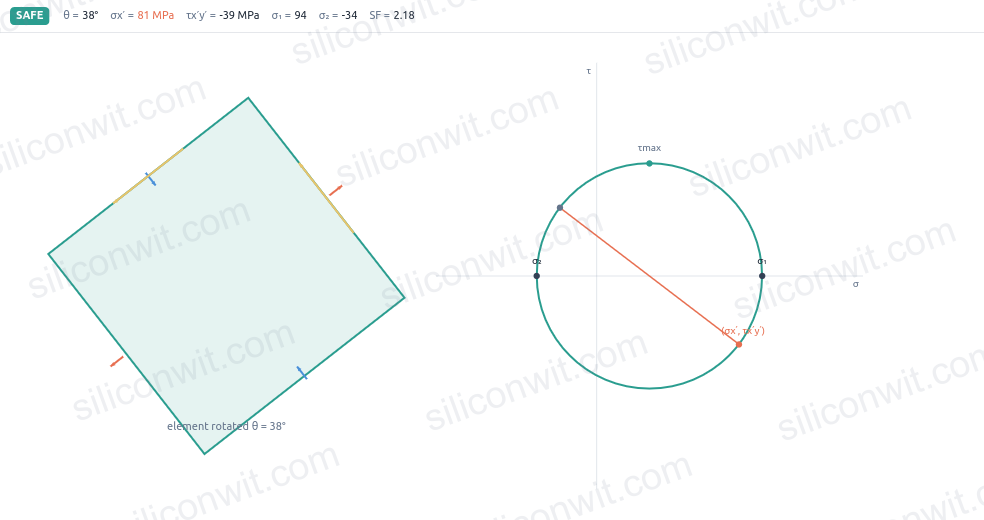
🔧 Application: Universal Joint Pin Analysis

Let’s analyze a critical universal joint pin under complex loading.


System Parameters:

  • Heavy-duty robotic universal joint pin (critical drive component)
  • Pin diameter: 25 mm (solid circular cross-section)
  • Material: Steel 4340 (σ_yield = 470 MPa, σ_ultimate = 745 MPa)
  • Applied torque: T = 500 N·m
  • Bending moment: M = 200 N·m (from joint angulation)
  • Contact pressure: 50 MPa (localized bearing load)
  • Safety factor: 4 (industrial environment)

Step 1: Calculate Individual Stress Components

Click to reveal individual stress component calculations
  1. Cross-sectional properties:

  2. Bending stress at surface:

  3. Torsional shear stress:

  4. Contact stress (localized bearing load):

Step 2: Principal Stress Analysis Using Mohr’s Circle

Click to reveal Mohr’s circle and principal stress calculations
  1. Stress state at critical point:

    • σ_x = 130.4 MPa (tension from bending)
    • σ_y = -50 MPa (compression from contact)
    • τ_xy = 163.2 MPa (from torsion)
  2. Mohr’s circle parameters:

  3. Principal stresses:

  4. Maximum shear stress:

Step 3: Apply Failure Theories and Design Assessment

Click to reveal failure theory analysis
  1. Maximum Normal Stress Theory:

    Result: Fails criterion ❌ (226.6 > 117.5 MPa)

  2. Maximum Shear Stress Theory (Tresca):

    Result: Fails criterion ❌ (186.4 > 58.75 MPa)

  3. von Mises Equivalent Stress:

    Result: Fails criterion ❌ (Actual SF = 1.37)

  4. Critical design assessment:

    All failure theories indicate current pin design is inadequate Universal joint pin requires immediate redesign to prevent failure

🔧 Engineering Problems

Problem 1: Pressure Vessel Joint Analysis

A spherical pressure vessel joint experiences complex stress states from internal pressure and thermal effects, requiring principal stress analysis.

Given:

  • Spherical pressure vessel: inner radius R = 500 mm, wall thickness t = 20 mm
  • Internal pressure: p = 2.5 MPa
  • Additional thermal stress: σ_thermal = 50 MPa (tangential direction)
  • Material: Steel (σ_yield = 250 MPa, σ_ultimate = 400 MPa)
  • Safety factor required: 3.0

Find: Principal stresses and safety factor using von Mises criterion.

Click to reveal solution
  1. Calculate pressure-induced stresses

    For thin-walled spherical pressure vessel:

    • Hoop stress: σ₁ = σ₂ = pR/(2t) = (2.5 × 500)/(2 × 20) = 31.25 MPa
    • Radial stress: σ₃ ≈ 0 (thin wall assumption)
  2. Add thermal stress components

    Combined stress state:

    • σ₁ = 31.25 + 50 = 81.25 MPa (tangential)
    • σ₂ = 31.25 MPa (tangential)
    • σ₃ = 0 MPa (radial)
  3. Identify principal stresses

    Since stresses are aligned with coordinate axes:

    • σ₁ = 81.25 MPa (maximum principal stress)
    • σ₂ = 31.25 MPa (intermediate principal stress)
    • σ₃ = 0 MPa (minimum principal stress)
  4. Apply von Mises failure criterion

    σ_eq = √[(σ₁-σ₂)² + (σ₂-σ₃)² + (σ₃-σ₁)²]/√2 σ_eq = √[(81.25-31.25)² + (31.25-0)² + (0-81.25)²]/√2 σ_eq = √[2500 + 976.6 + 6601.6]/√2 = 71.4 MPa

  5. Calculate safety factor

    SF = σ_yield/σ_eq = 250/71.4 = 3.50 Required SF = 3.0, Actual SF = 3.50 ✓ (Design adequate)

Problem 2: Shaft with Keyway Under Combined Loading

A motor shaft with a keyway experiences combined bending and torsion, creating a complex stress state requiring Mohr’s circle analysis.

Given:

  • Solid circular shaft: diameter d = 50 mm
  • Keyway: 12 mm wide × 6 mm deep (standard)
  • Bending moment: M = 800 N·m
  • Torque: T = 1200 N·m
  • Material: Steel 4140 (σ_yield = 415 MPa)
  • Stress concentration factor for keyway: Kt = 2.5

Find: Principal stresses at keyway location and safety factor.

Click to reveal solution
  1. Calculate nominal stresses

    At keyway location on shaft surface:

    • Bending stress: σ = Mc/I = (800×10³×25)/(π×50⁴/64) = 32.7 MPa
    • Torsional shear: τ = Tr/J = (1200×10³×25)/(π×50⁴/32) = 24.5 MPa
  2. Apply stress concentration

    Keyway amplifies stresses:

    • σ_max = Kt × σ = 2.5 × 32.7 = 81.8 MPa
    • τ_max = Kt × τ = 2.5 × 24.5 = 61.3 MPa
  3. Calculate principal stresses

    For combined normal and shear stress:

    • σ_avg = σ_max/2 = 81.8/2 = 40.9 MPa
    • σ₁ = σ_avg + √(σ_avg² + τ_max²) = 40.9 + √(40.9² + 61.3²) = 114.5 MPa
    • σ₂ = σ_avg - √(σ_avg² + τ_max²) = 40.9 - 73.6 = -32.7 MPa
  4. Determine maximum shear stress

    τ_max = (σ₁ - σ₂)/2 = (114.5 - (-32.7))/2 = 73.6 MPa

  5. Apply von Mises criterion

    σ_eq = √(σ₁² - σ₁σ₂ + σ₂²) = √(114.5² - 114.5×(-32.7) + (-32.7)²) = 128.2 MPa SF = 415/128.2 = 3.24 ✓ (Adequate safety factor)

Problem 3: Bolted Joint Under Eccentric Loading

A bolted connection experiences eccentric loading creating non-uniform stress distribution requiring principal stress analysis for the most critical bolt.

Given:

  • Bolt material: Steel Grade 8.8 (σ_yield = 640 MPa)
  • Bolt diameter: M12 (nominal diameter 12 mm)
  • Tensile load: F = 8000 N (eccentric, creates additional bending)
  • Bending moment on bolt: M = 96 N·m (from load eccentricity)
  • Thread stress concentration: Kt = 3.0
  • Safety factor required: 4.0

Find: Principal stresses in bolt and design adequacy.

Click to reveal solution
  1. Calculate bolt cross-sectional properties

    For M12 bolt (tensile stress area):

    • As = 84.3 mm² (standard value for M12)
    • Minor diameter: d = 10.106 mm
    • Section modulus: S = πd³/32 = π(10.106)³/32 = 101.4 mm³
  2. Calculate nominal stresses

    Direct tensile stress: σ_t = F/As = 8000/84.3 = 94.9 MPa Bending stress: σ_b = M/S = 96×10³/101.4 = 946.7 MPa

  3. Combine stresses and apply stress concentration

    Total tensile stress: σ_total = σ_t + σ_b = 94.9 + 946.7 = 1041.6 MPa With stress concentration: σ_max = Kt × σ_total = 3.0 × 1041.6 = 3124.8 MPa

  4. Identify principal stress state

    Uniaxial tension case:

    • σ₁ = 3124.8 MPa (maximum tensile)
    • σ₂ = σ₃ = 0 MPa Von Mises equivalent: σ_eq = σ₁ = 3124.8 MPa
  5. Check safety factor

    SF = σ_yield/σ_eq = 640/3124.8 = 0.20 Required SF = 4.0, Actual SF = 0.20 ⚠️ (Severely inadequate - redesign required)

📋 Course Completion Summary

Congratulations! You have completed Mechanics of Materials I & II with a comprehensive systems-based approach.

Knowledge Mastered

Part I: Foundations (Units 1.1-1.6)

  • ✅ Stress and strain fundamentals through crank-slider mechanisms
  • ✅ Material behavior analysis in CNC actuator systems
  • ✅ Multi-material compound systems in linear actuators
  • ✅ Thermal stress effects in heated piston-cylinder interfaces
  • ✅ Torsional analysis in Geneva mechanism crankshafts
  • ✅ Pressure vessel design for pneumatic actuator systems

Part II: Bending & Complex Loading (Units 2.1-2.6)

  • ✅ Shear force and bending moment analysis in robotic arms
  • ✅ Bending stress calculations in cantilever gripper systems
  • ✅ Beam deflection prediction for precision CNC spindles
  • ✅ Combined loading analysis in robotic wrist joints
  • ✅ Composite beam behavior in CNC machine structures
  • ✅ Principal stress analysis and failure prediction in universal joints

Professional Competencies Developed

Systems Integration

Connect solid mechanics theory to real mechatronic applications Design components that function reliably in complex systems

Industry-ready skills

Failure Prevention

Predict failure modes before they occur in operation Apply appropriate safety factors for reliable design

Risk mitigation expertise

Optimization Thinking

Balance strength, weight, cost, and performance requirements Iterate designs based on comprehensive stress analysis

Design optimization

Your Next Steps

Apply this knowledge to:

  • Advanced mechatronics projects requiring structural analysis
  • Multi-physics simulations combining stress, thermal, and dynamic effects
  • Failure analysis investigations in existing systems
  • Design optimization projects balancing multiple objectives

You are now equipped with the solid mechanics foundation essential for successful mechatronic system design and analysis!

Comments

© 2021-2025 SiliconWit. All rights reserved.