Skip to content

Lesson 2.5: Composite and Built-up Beam Systems

🎯 Learning Objectives

By the end of this lesson, you will be able to:

  1. Analyze composite beams made of different materials using the transformed section method
  2. Locate the neutral axis in composite beam cross-sections
  3. Calculate bending stresses in each material of a composite system
  4. Design hybrid structures for optimal strength-to-weight performance

🔧 Real-World System Problem: CNC Machine Bed Structure

High-precision CNC machines require extremely rigid bed structures to maintain accuracy during cutting operations. Modern CNC beds often use composite construction - combining steel reinforcement with aluminum casting to achieve optimal stiffness, weight, and thermal stability while managing cost.

System Description

CNC Machine Bed Components:

  • Steel Reinforcement Beams (high stiffness backbone structure)
  • Aluminum Casting (lightweight material filling and mounting surfaces)
  • Composite Cross-Section (steel beams encased in aluminum)
  • Precision Ways (guided surfaces for machine tools)
  • Vibration Damping (integrated damping materials)

The Composite Challenge

During machining operations, the CNC bed experiences:

Engineering Question: How do we analyze the stress distribution in a composite CNC bed where steel reinforcement beams are encased in aluminum, and how do we ensure both materials work together effectively under bending loads?

Why Composite Beam Analysis Matters

Consequences of Poor Composite Design:

  • Interfacial failure between steel and aluminum layers
  • Uneven stress distribution leading to premature failure
  • Excessive deflection reducing machining accuracy
  • Thermal stress cracking from differential expansion

Benefits of Proper Composite Analysis:

  • Optimized material usage leveraging each material’s strengths
  • Predictable load sharing between different materials
  • Enhanced structural performance compared to single materials
  • Cost-effective design balancing performance and economics

📚 Fundamental Theory: Composite Beam Mechanics

Basic Composite Beam Assumptions

For composite beams with perfect bonding between materials:

  1. Plane sections remain plane during bending
  2. No slip occurs at material interfaces
  3. Strain is continuous across the cross-section
  4. Each material follows its own stress-strain relationship

The Transformed Section Method

Since different materials have different elastic moduli, we transform the composite section into an equivalent single-material section:

🔄 Transformation Ratio Formula

Where:

  • = Transformation ratio (dimensionless)
  • = Elastic modulus of material to be transformed
  • = Elastic modulus of reference material

Physical Meaning: The transformation ratio allows us to convert a composite beam into an equivalent single-material beam by adjusting the width of one material based on stiffness differences.

Composite Beam Analysis Steps

Transform one material to the reference material:

  • Choose reference material (usually softer)
  • Calculate transformation ratio n = E₂/E₁
  • Transform width: b₂,transformed = n × b₂,actual

🔧 Application: CNC Bed Composite Beam Analysis

Let’s analyze a realistic CNC bed cross-section step by step.
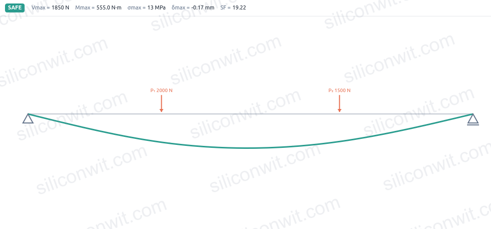

System Parameters:

  • Hybrid CNC machine bed (steel I-beam reinforcement in aluminum casting)
  • Steel I-beam: 150 mm × 200 mm × 12 mm flanges, 8 mm web, E₁ = 200 GPa, σ_yield = 250 MPa
  • Aluminum casting: 300 mm wide × 250 mm tall, E₂ = 70 GPa, σ_yield = 140 MPa
  • Span length: 2000 mm (simply supported)
  • Applied load: w = 50 kN uniform distributed load
  • Safety factor: 2.0

Step 1: Calculate Transformation Ratio

Click to reveal transformation ratio calculations
  1. Choose aluminum as reference material:

  2. Transform steel section to equivalent aluminum:

    • Steel I-beam actual: 150 mm flanges, 8 mm web
    • Steel I-beam transformed: 150 × 2.86 = 429 mm flanges, 8 × 2.86 = 23 mm web
  3. Analysis approach:

    Analyze transformed section as all-aluminum, then convert steel stresses using transformation ratio

Step 2: Locate Neutral Axis of Transformed Section

Click to reveal neutral axis calculations
  1. Aluminum region (original):

    • Total area minus steel: A₁ = (300×250) - (150×200-8×176) = 46,408 mm²
    • Centroid from bottom: ȳ₁ ≈ 125 mm (approximate due to steel cutout)
  2. Steel region (transformed to aluminum):

    • Transformed area: A₂ = 28,592 mm² (actual steel area)
    • Centroid from bottom: ȳ₂ = 125 mm (center of I-beam)
  3. Combined centroid location:

    Neutral axis at geometric center (125 mm from bottom) due to symmetry

Step 3: Calculate Maximum Bending Moment and Stresses

Click to reveal bending moment and stress calculations
  1. Maximum bending moment:

    For simply supported beam with uniform load:

  2. Transformed section moment of inertia:

    (calculated for composite section)

  3. Maximum distance from neutral axis:

    c = 125 mm (to top or bottom fiber)

Step 4: Calculate Stresses and Safety Factors

Click to reveal stress and safety factor calculations
  1. Stress in aluminum regions:

  2. Stress in steel regions:

  3. Safety factor assessment:

    • Aluminum: SF = 140/14.9 = 9.4 ✅ Very conservative
    • Steel: SF = 250/42.6 = 5.9 ✅ Safe design
    • Both exceed required SF = 2.0
  4. Load distribution analysis:

    Steel carries 2.86× more stress per unit strain, efficiently using its higher strength

🔧 Engineering Problems

Problem 1: Steel-Concrete Composite Beam

A composite beam consists of a steel I-beam with a concrete slab cast on top, used in building construction.

Given:

  • Steel I-beam: W200×36 (A = 4580 mm², I = 40.5×10⁶ mm⁴, centroid 100 mm from bottom)
  • Concrete slab: 1000 mm wide × 100 mm thick, cast on steel top flange
  • Simply supported span: L = 6000 mm
  • Uniform load: w = 15 kN/m (including self-weight)
  • Materials: Steel E₁ = 200 GPa, Concrete E₂ = 25 GPa
  • Perfect bond assumed between steel and concrete

Find: Maximum stresses in both steel and concrete.

Click to reveal solution
  1. Calculate transformation ratio

    Using steel as reference material: n = E_concrete/E_steel = 25/200 = 0.125 Transformed concrete width: b_t = n × 1000 = 125 mm

  2. Locate neutral axis of composite section

    For steel I-beam: A₁ = 4580 mm², ȳ₁ = 100 mm (from bottom) For concrete slab: A₂ = 125 × 100 = 12,500 mm², ȳ₂ = 250 mm (from bottom)

    ȳ = (A₁ȳ₁ + A₂ȳ₂)/(A₁ + A₂) = (4580×100 + 12,500×250)/(4580 + 12,500) = 202 mm

  3. Calculate composite moment of inertia

    Using parallel axis theorem for transformed section: I_composite = I_steel + A₁d₁² + A₂d₂² I_composite = 40.5×10⁶ + 4580×(202-100)² + 12,500×(250-202)² I_composite = 40.5×10⁶ + 47.6×10⁶ + 28.8×10⁶ = 116.9×10⁶ mm⁴

  4. Calculate maximum bending moment

    For simply supported beam: M_max = wL²/8 = 15×6²/8 = 67.5 kN·m

  5. Calculate stresses

    Steel (bottom): σ_s = M×c_s/I = 67.5×10⁶×202/116.9×10⁶ = 116.7 MPa Concrete (top): σ_c = (M×c_c/I) = 67.5×10⁶×48/116.9×10⁶ = 27.7 MPa (before transformation correction)

Problem 2: Aluminum-Steel Hybrid Beam

A lightweight beam combines aluminum flanges with a steel web for optimal strength-to-weight ratio in aerospace applications.

Given:

  • Steel web: 200 mm high × 8 mm thick (E₁ = 200 GPa)
  • Aluminum flanges: 150 mm wide × 20 mm thick, top and bottom (E₂ = 70 GPa)
  • Cantilever beam length: L = 1200 mm
  • Point load: P = 5000 N at free end
  • Perfect bonding between materials

Find: Maximum bending stresses in steel and aluminum components.

Click to reveal solution
  1. Transform aluminum to equivalent steel

    Transformation ratio: n = E_aluminum/E_steel = 70/200 = 0.35 Transformed aluminum flange width: b_t = 150 × 0.35 = 52.5 mm

  2. Calculate transformed section properties

    Due to symmetry, neutral axis is at mid-height (120 mm from bottom)

    • Steel web area: A₁ = 200 × 8 = 1600 mm²
    • Aluminum flange areas: A₂ = 2 × (52.5 × 20) = 2100 mm²
  3. Calculate moment of inertia of transformed section

    I_transformed = I_web + I_flanges + Ad² terms I_transformed = (8×200³)/12 + 2×[(52.5×20³)/12 + 52.5×20×100²] I_transformed = 5.33×10⁶ + 2×[35,000 + 10.5×10⁶] = 26.4×10⁶ mm⁴

  4. Calculate maximum bending moment

    For cantilever: M_max = P × L = 5000 × 1200 = 6×10⁶ N·mm

  5. Calculate stresses in both materials

    Steel web (at neutral axis level): σ_steel = 0 MPa Aluminum flanges: σ_aluminum = M×c/I_transformed × n⁻¹ σ_aluminum = (6×10⁶ × 120)/(26.4×10⁶) × (1/0.35) = 78.0 MPa

Problem 3: Carbon Fiber-Aluminum Composite Beam

A high-performance beam uses carbon fiber reinforcement bonded to aluminum structure for maximum stiffness with minimal weight.

Given:

  • Aluminum beam: rectangular 60 mm wide × 80 mm thick (E₁ = 70 GPa)
  • Carbon fiber strips: 60 mm wide × 3 mm thick, bonded to top and bottom (E₂ = 150 GPa)
  • Simply supported span: L = 800 mm
  • Uniform distributed load: w = 2000 N/m
  • Perfect bond between materials

Find: Stress distribution and maximum stresses in each material.

Click to reveal solution
  1. Calculate transformation ratio

    Using aluminum as reference: n = E_CF/E_Al = 150/70 = 2.14 Carbon fiber strips transform to equivalent aluminum: b_t = 60 × 2.14 = 128.6 mm

  2. Locate composite neutral axis

    Aluminum beam: A₁ = 60 × 80 = 4800 mm², ȳ₁ = 40 mm CF strips: A₂ = 2 × (128.6 × 3) = 771.6 mm², ȳ₂ = 42.5 mm (average of top/bottom)

    Due to near symmetry, neutral axis ≈ 40 mm from bottom

  3. Calculate composite moment of inertia

    I_aluminum = 60×80³/12 = 2.56×10⁶ mm⁴ I_CF = 2×[128.6×3³/12 + 128.6×3×38.5²] = 2×[96.4 + 57,200] = 114,600 mm⁴ I_total = 2.56×10⁶ + 0.115×10⁶ = 2.675×10⁶ mm⁴

  4. Calculate maximum bending moment

    M_max = wL²/8 = 2000 × 0.8²/8 = 160 N·m

  5. Determine maximum stresses

    Aluminum: σ_Al = Mc/I = 160×10³ × 40/(2.675×10⁶) = 2.39 MPa Carbon fiber: σ_CF = n × Mc/I = 2.14 × 160×10³ × 41.5/(2.675×10⁶) = 8.46 MPa

📋 Summary and Next Steps

In this lesson, you learned to:

  1. Apply the transformed section method to analyze composite beams
  2. Calculate stress distribution in multi-material systems
  3. Consider interface requirements and thermal effects
  4. Design composite structures for optimal performance

Key Design Insights:

  • Transformed section method handles different E values
  • Stiffer materials carry proportionally more stress
  • Interface bond strength is critical for composite action

Critical Formula: where

Coming Next: In Lesson 2.6, we’ll analyze principal stresses and failure criteria for critical stress evaluation in mechatronic joint design using Mohr’s circle analysis.

Comments

© 2021-2025 SiliconWit. All rights reserved.