Preventing hidden overload
In a parallel system, the stiffer material attracts more load than its area alone would suggest. Ignoring this can leave one material near its yield limit while the other is barely stressed.
When a load passes through two materials joined end to end, steel and aluminum for example, each material carries a different stress and stretches by a different amount. Ignoring this mismatch leads to designs where one segment yields while the other is barely loaded, or where differential expansion under temperature changes introduces unexpected forces at the joint. In this lesson you will analyze three compound systems: a linear actuator rod (series, unequal areas), a steel-core aluminum-tube column (parallel, equal shortening), and a stepped tie rod (series, total elongation as a sum). #CompoundBars #LoadSharing #MultiMaterial
By the end of this lesson, you will be able to:
Industrial machines combine materials deliberately: a stiff steel core to carry the bulk of a compressive load, a lighter aluminum jacket to add cross-sectional area at low cost, or a steel-aluminum stepped rod to save weight along the lightly stressed length. Each combination falls into one of two fundamental arrangements, and the analysis depends on which one it is.
Engineering Question: When a single axial load is applied to a system made of two or more materials, how does the load split between them, and how much does each material deform? The answer depends entirely on whether the materials deform together (parallel) or the same force passes through them in succession (series).
Preventing hidden overload
In a parallel system, the stiffer material attracts more load than its area alone would suggest. Ignoring this can leave one material near its yield limit while the other is barely stressed.
Weight and cost optimization
Using aluminum where stresses are low and steel only where they are high can cut component weight by 30 to 40 percent without compromising strength.
Deformation compatibility
Whenever two materials are bonded or bolted together, their deformations must match at every interface. Violating this constraint is the most common error in compound bar analysis.
System-level reliability
A compound rod that yields in one material will redistribute load to the other, often catastrophically. The analysis predicts and prevents that redistribution.
Every compound bar problem reduces to one of two arrangements, and getting the right one is the first step.
In a parallel compound bar the materials share the same length and the same end conditions: both shorten (or lengthen) by exactly the same amount
Parallel: compatibility and load split
Because both materials shorten by
The stress in each material follows from Hooke’s law:
Equilibrium requires the loads to sum to the applied total:
Solving for the load carried by material
The load splits in proportion to the axial stiffness
In a series compound bar, the axial force is the same in every segment (from equilibrium of any cross-section between the applied loads). The deformations of the segments add up to give the total elongation.
Series: same force, deflections add
For each segment
Total elongation:
Each segment has its own stress level because the areas differ, but the force is the same throughout.
An industrial linear actuator rod is made in two sections joined end to end. The steel section is short and compact, sized for the confined end of the actuator; the aluminum section is longer and wider, reducing overall weight along the stroke. A tensile force is applied at one end and reacted at the other, so the same force passes through both sections. This is a series arrangement.
Steel section area:
Aluminum section area:
Axial stiffness of each section (units: N/mm):
Load in each section (same force throughout in a series rod, but cross-check via stiffness confirms it is indeed a series system where
Because this is a series arrangement,
Stress in the steel section:
Stress in the aluminum section:
Safety factors:
Both exceed the required 3.0 comfortably. The rod is sized conservatively, as expected for a part that also sees dynamic loading. ✅
Elongation of the steel section:
Elongation of the aluminum section:
Total rod elongation:
Note that the aluminum section stretches three times as much as the steel section, even though the force is the same. The aluminum section is both longer and less stiff per unit area. ✅
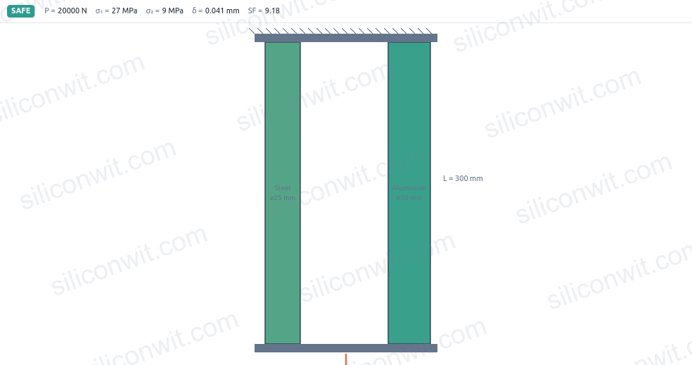
A structural column is built by sliding a solid steel rod through the centre of an aluminum tube and compressing both between the same two end plates. Both materials shorten by the same amount (they share the same end fixings), so the load splits by axial stiffness. This is a parallel arrangement.
Load a compound steel-and-aluminum bar in the simulator and watch the stiffer steel draw more than its area share of the load:
Steel rod area:
Aluminum tube area:
Because both materials have the same length
Even though the aluminum tube has nearly twice the cross-sectional area of the steel rod (
Load on the steel rod:
Load on the aluminum tube:
Steel carries 61.6 percent of the total load despite occupying only
Compressive stress in the steel rod:
Compressive stress in the aluminum tube:
Safety factors:
Both materials have adequate margin. The steel rod is the governing element at SF = 3.34. ✅
Common strain (the same for both, by compatibility):
Shortening of the column:
Verification via the aluminum:
Both materials confirm the same strain, which is the compatibility check. ✅
A stepped tie rod carries a single tensile force from one end to the other through two segments of different material and diameter. The force is the same in every cross-section (series arrangement), so the stresses differ because the areas differ, and the total elongation is the sum of the two segment elongations.
Steel segment area:
Aluminum segment area:
The same force
Safety factors:
The steel segment is the critical one; its safety factor is 3.67. ✅
Elongation of the steel segment:
Elongation of the aluminum segment:
Total elongation:
The aluminum segment stretches 70 percent more than the steel segment, even though it is only 33 percent longer, because its modulus is less than half of steel’s. ✅
Identify the arrangement first
Before writing any equation, decide whether the materials deform together (parallel) or carry the same force in sequence (series). The governing equations are completely different for the two cases.
Load splits by EA in parallel
In a parallel system, use
Check every material separately
Each segment has its own stress and its own safety factor against yield. Passing one does not guarantee the other passes. In most compound systems the materials have different yield strengths, so both checks are needed.
Sum deflections in series, share in parallel
Total elongation in a series bar is the sum of segment elongations. In a parallel bar, one common deflection closes the problem. Confusing the two is the source of most compound-bar errors.
| Application | Arrangement | Key results | Governing SF |
|---|---|---|---|
| Linear actuator rod (steel 25 mm + alum 30 mm, 20 kN) | Series | 9.5 (alum) | |
| Steel core + alum tube column (120 kN, 250 mm) | Parallel | 3.34 (steel) | |
| Stepped tie rod (steel 20 mm + alum 30 mm, 30 kN) | Series | 3.67 (steel) |
All three worked examples required only the formulas
Next, Thermal Stresses and Strains extends the compound bar framework to temperature loading, where no external force is applied but constrained thermal expansion drives internal stresses that can be large enough to yield the softer material.
Comments