Stress transformation
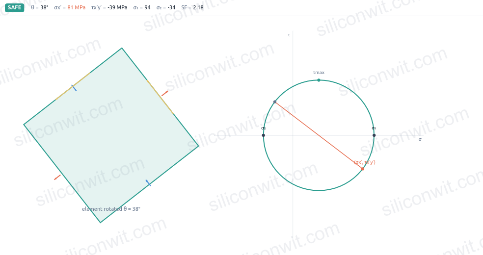
Drag the element angle and watch the face stresses change while the principal stresses stay fixed. The point on the circle is the current face stress; the charts plot the full sweep through a half-turn.
このコンテンツはまだ日本語訳がありません。
Real components rarely carry pure tension or pure shear. A shaft bends and twists at once, a bracket pulls on one face while shearing on another, and the plane that actually fails is almost never the plane you drew. Mohr’s circle is the tool that turns this mess into one picture: every orientation of the stress element is a single point riding around one circle, the points where the circle crosses the axis are the principal stresses, and the top of the circle is the worst shear. This simulator lets you rotate the element and watch that point move, read the principal stresses and their orientation, and check the state against von Mises and Tresca with a live safety factor. #MohrsCircle #StressTransformation #FailureAnalysis
Open SimulatorStress transformation
Drag the element angle and watch the face stresses change while the principal stresses stay fixed. The point on the circle is the current face stress; the charts plot the full sweep through a half-turn.
Principal stresses and orientation
Read the principal stresses where shear vanishes, and the angle to that orientation, computed analytically rather than scaled off a drawing.
Maximum shear
Find the maximum in-plane shear at the top of the circle and the plane it acts on, forty-five degrees from the principal orientation.
Failure check
Compare the state against a material yield with von Mises and Tresca, and read a live safety factor and a Safe or Yields verdict.
Element synced to the circle The rotating stress element and the moving point on the Mohr circle update together, so the abstract construction is tied to a physical orientation at all times.
Live principal and shear readouts Principal stresses, principal angle, maximum shear, and the max-shear plane recompute as you drag any input.
Four analysis charts Normal stress and shear stress against rotation angle, plus the state placed in principal-stress space against the yield envelope and a load-margin chart.
von Mises and Tresca Switch criteria and enter a yield strength; the panel reports the equivalent stress and a safety factor for a plane-stress state.
Five stress-state presets Pure tension, pure shear, equal biaxial, general plane stress, and combined bending plus torsion, each a realistic starting point.
Live A/B comparison Save State A, change the stresses, and overlay state B on every chart to compare two loadings directly.
Downloadable resources A design-data sheet, the full transformation dataset as CSV (both states when you compare two), and a complete lab report with watermark-free diagram and charts.
| Preset | σx (MPa) | σy (MPa) | τxy (MPa) | Represents |
|---|---|---|---|---|
| Pure tension | 120 | 0 | 0 | Uniaxial bar in tension |
| Pure shear | 0 | 0 | 80 | Thin tube in torsion |
| Biaxial (equal) | 100 | 100 | 0 | Sphere wall, equal in-plane stress |
| General plane stress | 80 | -20 | 40 | Mixed normal and shear state |
| Bending + torsion | 140 | 0 | 70 | Shaft surface under combined load |
Circle centre (average normal stress) and radius:
sigma_avg = (sx + sy) / 2R = sqrt( ((sx - sy)/2)^2 + txy^2 )Principal stresses and the orientation to them:
sigma_1,2 = sigma_avg +/- Rtan(2*theta_p) = 2*txy / (sx - sy)Maximum in-plane shear and its plane:
tau_max = Rtheta_s = theta_p - 45 degreesStresses on a face rotated by theta from the x-axis (the point that rides the circle):
sigma_x' = sigma_avg + ((sx - sy)/2)*cos(2*theta) + txy*sin(2*theta)tau_x'y' = -((sx - sy)/2)*sin(2*theta) + txy*cos(2*theta)Failure check for a plane-stress state (the out-of-plane principal stress is zero):
von Mises: sigma_vm = sqrt( s1^2 - s1*s2 + s2^2 )Tresca: sigma_tr = max( |s1 - s2|, |s1|, |s2| )safety factor = yield / equivalent stressWork through the Stress Transformation Experiments lesson for structured, Python-verified exercises:
Comments