Junction-to-Case (R_jc)
Given by the component datasheet. For a typical power MOSFET in TO-220 package:
A chip rated for 125 degrees C junction temperature will throttle, glitch, or fail permanently if the heat sink cannot dissipate its power budget. Picking a heat sink from a catalog is a gamble unless you understand the full thermal resistance chain from junction to ambient, and the right fin geometry depends on airflow, orientation, and available space in ways that are not obvious from a datasheet alone. In this lesson you will model that resistance chain from first principles, compare straight-fin, pin-fin, and radial fin geometries in CadQuery, and sweep parameters with Python to build thermal performance maps that show exactly which configuration keeps your chip cool. #ThermalDesign #HeatSink #CadQuery
By the end of this lesson, you will be able to:
Thermal Resistance Chain (Junction to Ambient) ────────────────────────────────────────── Tj (junction) │ ├── Rjc (junction to case) 0.5-3.0 C/W │ Package type, die attach │ ├── Rcs (case to sink) 0.1-2.0 C/W │ Thermal paste or pad │ ├── Rsa (sink to ambient) ← We design this │ Fin geometry, airflow │ ▼ Ta (ambient air)
Tj = Ta + Q × (Rjc + Rcs + Rsa)
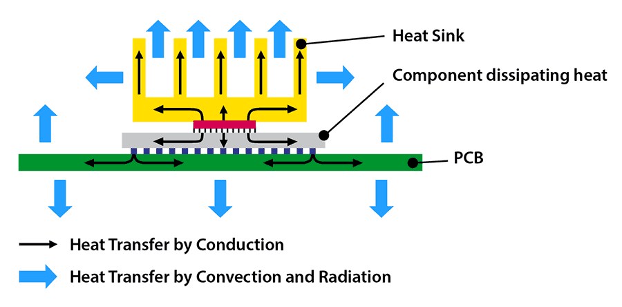
Analogy: series electrical circuit Q (watts) = I (amps) dT (degrees) = V (volts) R_thermal = R_electricalHeat flows from the semiconductor junction through a series of thermal resistances to the surrounding air. Each resistance is analogous to an electrical resistor in a series circuit.
The total thermal resistance from junction to ambient is:
where:
The junction temperature is then:
where
Junction-to-Case (R_jc)
Given by the component datasheet. For a typical power MOSFET in TO-220 package:
Case-to-Sink (R_cs)
Controlled by the thermal interface material (TIM). Thermal paste:
Sink-to-Ambient (R_sa)
This is what we design and optimize. Depends on: fin geometry, surface area, airflow conditions, material conductivity. Typical range:
Design Target
Work backward from the maximum junction temperature. Given
Consider a voltage regulator dissipating 5W with these constraints:
"""Design target calculation: maximum allowable R_sa."""
# Component specifications (from datasheet)T_j_max = 125.0    # °C, maximum junction temperatureQ = 5.0            # W, power dissipationT_ambient = 40.0   # °C, worst-case ambient temperature
# Thermal resistances (from datasheet and TIM selection)R_jc = 1.5         # °C/W, junction-to-case (TO-220 package)R_cs = 0.3         # °C/W, thermal paste interface
# Required total resistanceR_total_max = (T_j_max - T_ambient) / Qprint(f"Maximum total R_total: {R_total_max:.1f} °C/W")
# Required sink-to-ambient resistanceR_sa_max = R_total_max - R_jc - R_csprint(f"Required R_sa ≤ {R_sa_max:.1f} °C/W")
# With 20% safety marginR_sa_target = R_sa_max * 0.8print(f"Design target R_sa: {R_sa_target:.1f} °C/W")
Maximum total R_total: 17.0 °C/WRequired R_sa ≤ 15.2 °C/WDesign target R_sa: 12.2 °C/WThis is a comfortable target for a moderately-sized heat sink with natural convection. For higher power (20W+), the target
For a heat sink without a fan, the dominant heat transfer mode is natural convection, where warm air rises along the fin surfaces, drawing cool air in from below.
The heat transfer coefficient
For a vertical isothermal plate in air, the Churchill-Chu correlation gives:
where the Rayleigh number is:
and
"""Natural convection thermal resistance calculator for heat sinks.Uses Churchill-Chu correlation for vertical plates."""
import mathfrom dataclasses import dataclass
@dataclassclass AirProperties:    """    Dry air properties at a given film temperature.    Evaluated at T_film = (T_surface + T_ambient) / 2.    """    T_film: float       # K
    @property    def rho(self) -> float:        """Density [kg/m^3] — ideal gas law."""        return 101325.0 / (287.058 * self.T_film)
    @property    def cp(self) -> float:        """Specific heat [J/(kg·K)] — nearly constant for air."""        return 1007.0
    @property    def mu(self) -> float:        """Dynamic viscosity [Pa·s] — Sutherland's law."""        T = self.T_film        return 1.716e-5 * (T / 273.15) ** 1.5 * (273.15 + 110.4) / (T + 110.4)
    @property    def nu(self) -> float:        """Kinematic viscosity [m^2/s]."""        return self.mu / self.rho
    @property    def k(self) -> float:        """Thermal conductivity [W/(m·K)]."""        T = self.T_film        return 0.02414 * (T / 273.15) ** 0.8
    @property    def Pr(self) -> float:        """Prandtl number [-]."""        return self.mu * self.cp / self.k
    @property    def beta(self) -> float:        """Volumetric thermal expansion coefficient [1/K]."""        return 1.0 / self.T_film
def nusselt_vertical_plate(Ra: float, Pr: float) -> float:    """    Churchill-Chu correlation for natural convection from a vertical plate.    Valid for all Ra (laminar and turbulent).
    Nu = [0.825 + 0.387 * Ra^(1/6) / (1 + (0.492/Pr)^(9/16))^(8/27)]^2    """    bracket = (1.0 + (0.492 / Pr) ** (9.0 / 16.0)) ** (8.0 / 27.0)    Nu = (0.825 + 0.387 * Ra ** (1.0 / 6.0) / bracket) ** 2    return Nu
def thermal_resistance_plate_fin(    n_fins: int,    fin_height: float,      # m (vertical extent of fin)    fin_length: float,       # m (horizontal extent, base to tip)    fin_thickness: float,    # m    base_width: float,       # m (heat sink footprint width)    base_depth: float,       # m (heat sink footprint depth)    T_surface: float = 80.0, # °C, assumed surface temperature    T_ambient: float = 25.0, # °C) -> dict:    """    Calculate thermal resistance for a straight rectangular fin heat sink    under natural convection.
    Returns dict with R_sa, h_avg, total surface area, and intermediate values.    """    # Film temperature for air properties    T_film_K = ((T_surface + T_ambient) / 2.0) + 273.15    air = AirProperties(T_film_K)
    # Temperature difference    dT = T_surface - T_ambient
    # Characteristic length = fin height (vertical)    L_char = fin_height
    # Rayleigh number    g = 9.81  # m/s^2    Ra = (g * air.beta * dT * L_char ** 3) / (air.nu ** 2) * air.Pr
    # Nusselt number    Nu = nusselt_vertical_plate(Ra, air.Pr)
    # Average heat transfer coefficient    h_avg = Nu * air.k / L_char  # W/(m^2·K)
    # Fin spacing (center-to-center)    if n_fins > 1:        fin_spacing = (base_width - n_fins * fin_thickness) / (n_fins - 1)    else:        fin_spacing = base_width
    # Check if spacing is too tight (flow restriction)    # Elenbaas optimal spacing for natural convection:    # S_opt ≈ 2.71 * (L^0.25 / Ra_S^0.25) — simplified    # For practical purposes, spacing < 3mm severely restricts flow
    # Total fin surface area (both sides of each fin + base between fins)    fin_area = n_fins * 2 * fin_length * fin_height  # both sides    base_area = base_width * base_depth  # top of base plate    channel_area = (n_fins - 1) * fin_spacing * base_depth  # base between fins    total_area = fin_area + base_area + channel_area
    # Fin efficiency (for thin aluminum fins, efficiency is high)    # eta_fin = tanh(m*L) / (m*L), where m = sqrt(2*h/(k_fin*t))    k_fin = 205.0  # W/(m·K), aluminum 6061    m = math.sqrt(2 * h_avg / (k_fin * fin_thickness))    mL = m * fin_length    if mL > 0:        eta_fin = math.tanh(mL) / mL    else:        eta_fin = 1.0
    # Effective area (accounting for fin efficiency)    effective_area = eta_fin * fin_area + base_area + channel_area
    # Thermal resistance    R_sa = 1.0 / (h_avg * effective_area)
return { "R_sa": R_sa, "h_avg": h_avg, "Ra": Ra, "Nu": Nu, "fin_spacing_mm": fin_spacing * 1000, "total_area_cm2": total_area * 1e4, "effective_area_cm2": effective_area * 1e4, "eta_fin": eta_fin, "n_fins": n_fins, "fin_height_mm": fin_height * 1000, "fin_length_mm": fin_length * 1000, }Three fin geometries are commonly used in heat sink design. Each has distinct thermal and manufacturing characteristics.
The simplest and most common geometry. Parallel plate fins extending vertically from a flat base. Easy to manufacture by extrusion, machining, or 3D printing.
Advantages:
Disadvantages:
"""CadQuery: Straight rectangular fin heat sink."""
import cadquery as cq
def straight_fin_heatsink(    base_width: float = 50.0,    # mm    base_depth: float = 50.0,    # mm    base_height: float = 3.0,    # mm    n_fins: int = 11,    fin_height: float = 25.0,    # mm (tip to base)    fin_thickness: float = 1.5,  # mm) -> cq.Workplane:    """    Generate a straight rectangular fin heat sink.
    Fins are oriented along the Y-axis (depth direction),    distributed along the X-axis (width direction).    """    # Base plate    hs = (        cq.Workplane("XY")        .box(base_width, base_depth, base_height,             centered=(True, True, False))    )
    # Calculate fin positions (evenly distributed)    if n_fins > 1:        spacing = base_width / (n_fins - 1)        x_start = -base_width / 2    else:        spacing = 0        x_start = 0
    # Add each fin    for i in range(n_fins):        x_pos = x_start + i * spacing
        fin = (            cq.Workplane("XY")            .workplane(offset=base_height)            .center(x_pos, 0)            .rect(fin_thickness, base_depth)            .extrude(fin_height)        )
        hs = hs.union(fin)
    # Fillet the base-to-fin junctions for stress relief and airflow    # (small fillet at fin roots)    hs = hs.edges("|Y").edges(">Z").fillet(0.5)
    return hs
# Generate with default parametersheatsink_straight = straight_fin_heatsink( base_width=50.0, base_depth=50.0, base_height=3.0, n_fins=11, fin_height=25.0, fin_thickness=1.5,)Cylindrical or square pins arranged in a grid pattern. Pins provide omnidirectional airflow. The heat sink performs equally regardless of orientation, making pin fins ideal for natural convection where airflow direction is uncertain.
Advantages:
Disadvantages:
"""CadQuery: Pin-fin array heat sink."""
import cadquery as cqimport math
def pin_fin_heatsink(    base_width: float = 50.0,    # mm    base_depth: float = 50.0,    # mm    base_height: float = 3.0,    # mm    pin_diameter: float = 3.0,   # mm    pin_height: float = 25.0,    # mm    pin_spacing: float = 5.0,    # mm (center-to-center)    pin_shape: str = "round",    # "round" or "square") -> cq.Workplane:    """    Generate a pin-fin array heat sink.    Pins are arranged in a rectangular grid pattern.    """    # Base plate    hs = (        cq.Workplane("XY")        .box(base_width, base_depth, base_height,             centered=(True, True, False))    )
    # Calculate pin grid    margin = pin_spacing  # keep one spacing from edge    n_x = int((base_width - 2 * margin) / pin_spacing) + 1    n_y = int((base_depth - 2 * margin) / pin_spacing) + 1
    x_start = -(n_x - 1) * pin_spacing / 2    y_start = -(n_y - 1) * pin_spacing / 2
    # Create all pins as a single operation for performance    pin_centers = []    for ix in range(n_x):        for iy in range(n_y):            px = x_start + ix * pin_spacing            py = y_start + iy * pin_spacing            pin_centers.append((px, py))
    # Build pins    for (px, py) in pin_centers:        if pin_shape == "round":            pin = (                cq.Workplane("XY")                .workplane(offset=base_height)                .center(px, py)                .circle(pin_diameter / 2)                .extrude(pin_height)            )        else:  # square            pin = (                cq.Workplane("XY")                .workplane(offset=base_height)                .center(px, py)                .rect(pin_diameter, pin_diameter)                .extrude(pin_height)            )            # Chamfer pin tops for easier print            pin = pin.faces(">Z").edges().chamfer(0.3)
        hs = hs.union(pin)
    # Chamfer pin tops for airflow    # (done individually above for square pins)
    return hs
# Generate with default parametersheatsink_pin = pin_fin_heatsink(    base_width=50.0,    base_depth=50.0,    base_height=3.0,    pin_diameter=3.0,    pin_height=25.0,    pin_spacing=6.0,    pin_shape="round",)
# Pin count and surface arean_pins = 8 * 8 # approximately, for 50mm base with 6mm spacingpin_area_each = math.pi * 3.0 * 25.0 # mm^2 per pin (lateral surface)total_pin_area = n_pins * pin_area_eachprint(f"Pin count: {n_pins}")print(f"Total fin area: {total_pin_area:.0f} mm² = {total_pin_area/100:.1f} cm²")Fins radiate outward from a central hot spot, like spokes of a wheel. This geometry is optimal when heat is concentrated at a single point (e.g., directly above a BGA chip) and the heat sink is exposed to air from all sides.
Advantages:
Disadvantages:
"""CadQuery: Radial (sunflower) fin heat sink."""
import cadquery as cqimport math
def radial_fin_heatsink(    base_diameter: float = 60.0,  # mm    base_height: float = 3.0,     # mm    n_fins: int = 24,    fin_height: float = 20.0,     # mm    fin_thickness: float = 1.2,   # mm    inner_radius: float = 8.0,    # mm (hub radius, no fins inside)    outer_radius: float = 28.0,   # mm (fin tip radius)) -> cq.Workplane:    """    Generate a radial fin heat sink with fins radiating from center.
    Each fin is a thin plate oriented radially, extending from    inner_radius to outer_radius and rising fin_height above the base.    """    # Circular base plate    hs = (        cq.Workplane("XY")        .circle(base_diameter / 2)        .extrude(base_height)    )
    # Central hub (thicker section for thermal spreading)    hub = (        cq.Workplane("XY")        .workplane(offset=base_height)        .circle(inner_radius)        .extrude(fin_height * 0.3)  # hub is 30% of fin height    )    hs = hs.union(hub)
    # Add radial fins    angle_step = 360.0 / n_fins
    for i in range(n_fins):        angle_deg = i * angle_step        angle_rad = math.radians(angle_deg)
        # Fin center line direction        dx = math.cos(angle_rad)        dy = math.sin(angle_rad)
        # Fin is a thin box oriented along the radial direction        # Length = outer_radius - inner_radius        fin_length = outer_radius - inner_radius        fin_center_r = (inner_radius + outer_radius) / 2
        cx = fin_center_r * dx        cy = fin_center_r * dy
        fin = (            cq.Workplane("XY")            .workplane(offset=base_height)            .center(cx, cy)            .rect(fin_length, fin_thickness)            .extrude(fin_height)        )
        # Rotate fin to align with radial direction        # The fin is created along X, so rotate by the fin's angle        fin = fin.rotate((0, 0, 0), (0, 0, 1), angle_deg)
        hs = hs.union(fin)
    return hs
# Generate with default parametersheatsink_radial = radial_fin_heatsink( base_diameter=60.0, base_height=3.0, n_fins=24, fin_height=20.0, fin_thickness=1.2, inner_radius=8.0, outer_radius=28.0,)The core of thermal optimization is sweeping the design space: varying fin count, fin height, and fin spacing, then computing
"""Parameter sweep: fin count × fin height → thermal resistance map.Generates data for matplotlib contour plots."""
import numpy as np
def sweep_straight_fins(    base_width: float = 0.050,    # m (50mm)    base_depth: float = 0.050,    # m (50mm)    fin_thickness: float = 0.0015, # m (1.5mm)    fin_counts: list = None,    fin_heights: list = None,    T_surface: float = 80.0,    T_ambient: float = 25.0,) -> dict:    """    Sweep fin count and fin height, computing R_sa for each combination.
    Returns:        dict with 'fin_counts', 'fin_heights', 'R_sa' (2D array),        'spacing' (2D array), 'area' (2D array)    """    if fin_counts is None:        fin_counts = list(range(5, 31))          # 5 to 30 fins    if fin_heights is None:        fin_heights = np.linspace(0.010, 0.050, 20).tolist()  # 10-50mm
    R_sa_map = np.zeros((len(fin_heights), len(fin_counts)))    spacing_map = np.zeros_like(R_sa_map)    area_map = np.zeros_like(R_sa_map)
    for i, fh in enumerate(fin_heights):        for j, n in enumerate(fin_counts):            result = thermal_resistance_plate_fin(                n_fins=n,                fin_height=fh,                fin_length=fh,           # fin length = fin height for vertical fins                fin_thickness=fin_thickness,                base_width=base_width,                base_depth=base_depth,                T_surface=T_surface,                T_ambient=T_ambient,            )
            R_sa_map[i, j] = result["R_sa"]            spacing_map[i, j] = result["fin_spacing_mm"]            area_map[i, j] = result["total_area_cm2"]
    return {        "fin_counts": fin_counts,        "fin_heights_mm": [h * 1000 for h in fin_heights],        "R_sa": R_sa_map,        "spacing_mm": spacing_map,        "area_cm2": area_map,    }
# Run the sweepsweep = sweep_straight_fins()print(f"Sweep grid: {len(sweep['fin_heights_mm'])} heights × " f"{len(sweep['fin_counts'])} fin counts")print(f"R_sa range: {sweep['R_sa'].min():.2f} - {sweep['R_sa'].max():.2f} °C/W")"""Generate thermal performance maps as contour plots."""
import matplotlib.pyplot as pltimport matplotlib.ticker as tickerimport numpy as np
def plot_thermal_map(sweep: dict, R_sa_target: float = None): """ Create a filled contour plot of R_sa vs. fin count and fin height.
Args: sweep: Output from sweep_straight_fins() R_sa_target: Optional target R_sa line to overlay """ fig, axes = plt.subplots(1, 2, figsize=(14, 6))
N, H = np.meshgrid(sweep["fin_counts"], sweep["fin_heights_mm"]) R = sweep["R_sa"]
# --- Plot 1: Thermal Resistance Map --- ax1 = axes[0] cs1 = ax1.contourf(N, H, R, levels=20, cmap="RdYlBu_r") cbar1 = plt.colorbar(cs1, ax=ax1) cbar1.set_label("$R_{sa}$ [°C/W]", fontsize=12)
# Overlay contour lines with labels cl1 = ax1.contour(N, H, R, levels=10, colors="black", linewidths=0.5) ax1.clabel(cl1, inline=True, fontsize=8, fmt="%.1f")
# Target R_sa line if R_sa_target: ax1.contour(N, H, R, levels=[R_sa_target], colors="lime", linewidths=2, linestyles="--") ax1.text(sweep["fin_counts"][-1] - 2, sweep["fin_heights_mm"][-1] - 2, f"Target: {R_sa_target:.1f} °C/W", color="lime", fontsize=10, fontweight="bold", ha="right", va="top", bbox=dict(boxstyle="round", fc="black", alpha=0.7))
# Mark optimum (minimum R_sa) idx = np.unravel_index(R.argmin(), R.shape) ax1.plot(sweep["fin_counts"][idx[1]], sweep["fin_heights_mm"][idx[0]], "k*", markersize=15, label=f"Min R_sa = {R.min():.2f} °C/W") ax1.legend(loc="upper right")
ax1.set_xlabel("Number of Fins", fontsize=12) ax1.set_ylabel("Fin Height [mm]", fontsize=12) ax1.set_title("Thermal Resistance Map", fontsize=14)
# --- Plot 2: Fin Spacing Map (feasibility) --- ax2 = axes[1] S = sweep["spacing_mm"] cs2 = ax2.contourf(N, H, S, levels=20, cmap="viridis") cbar2 = plt.colorbar(cs2, ax=ax2) cbar2.set_label("Fin Spacing [mm]", fontsize=12)
# Mark minimum manufacturable spacing (e.g., 2mm for FDM) ax2.contour(N, H, S, levels=[2.0], colors="red", linewidths=2, linestyles="--") ax2.contour(N, H, S, levels=[3.0], colors="orange", linewidths=1.5, linestyles="--") ax2.text(sweep["fin_counts"][-1] - 1, 12, "2mm min (FDM)", color="red", fontsize=9, ha="right") ax2.text(sweep["fin_counts"][-1] - 1, 15, "3mm min (optimal flow)", color="orange", fontsize=9, ha="right")
ax2.set_xlabel("Number of Fins", fontsize=12) ax2.set_ylabel("Fin Height [mm]", fontsize=12) ax2.set_title("Fin Spacing (Manufacturability)", fontsize=14)
plt.tight_layout() plt.savefig("thermal_performance_map.png", dpi=150, bbox_inches="tight") plt.show() print("Saved: thermal_performance_map.png")
# Generate the plotsplot_thermal_map(sweep, R_sa_target=12.0)The thermal performance map reveals three key insights:
More fins reduce
Taller fins reduce
The feasibility boundary is set by fin spacing. For FDM 3D printing, the minimum practical spacing is about 2mm. For CNC extrusion, 1.5mm is achievable. The red line on the spacing map marks the manufacturing limit; any design above and to the right of this line is not producible.
With the sweep data, we can apply constraints and find the optimal design point.
"""Constrained optimization: minimize R_sa subject to manufacturing limits."""
import numpy as np
def find_optimal_heatsink(sweep: dict,                           min_spacing: float = 2.0,                           max_height: float = 40.0,                           max_fins: int = 25,                           R_sa_target: float = None) -> dict:    """    Find the configuration with minimum R_sa that satisfies all constraints.
    Args:        sweep: Parameter sweep results        min_spacing: Minimum fin spacing [mm] (manufacturing limit)        max_height: Maximum fin height [mm] (volume constraint)        max_fins: Maximum number of fins (cost constraint)        R_sa_target: If set, find the smallest heat sink meeting this target
    Returns:        dict with optimal parameters    """    R = sweep["R_sa"]    S = sweep["spacing_mm"]    fin_counts = np.array(sweep["fin_counts"])    fin_heights = np.array(sweep["fin_heights_mm"])
    # Create constraint mask    N_grid, H_grid = np.meshgrid(fin_counts, fin_heights)    feasible = (        (S >= min_spacing) &        (H_grid <= max_height) &        (N_grid <= max_fins)    )
    # Apply mask (set infeasible points to infinity)    R_feasible = np.where(feasible, R, np.inf)
    # Find minimum    idx = np.unravel_index(R_feasible.argmin(), R_feasible.shape)    i_h, i_n = idx
    optimal = {        "n_fins": int(fin_counts[i_n]),        "fin_height_mm": float(fin_heights[i_h]),        "fin_spacing_mm": float(S[i_h, i_n]),        "R_sa": float(R[i_h, i_n]),        "total_area_cm2": float(sweep["area_cm2"][i_h, i_n]),    }
    # Check if target is met    if R_sa_target:        optimal["meets_target"] = optimal["R_sa"] <= R_sa_target
    return optimal
# Find optimum with constraintsoptimal = find_optimal_heatsink(    sweep,    min_spacing=2.5,       # FDM-friendly spacing    max_height=35.0,       # keep it compact    max_fins=22,           # reasonable fin count    R_sa_target=12.0,      # our design target)
print("Optimal heat sink configuration:")print(f"  Fins:         {optimal['n_fins']}")print(f"  Fin height:   {optimal['fin_height_mm']:.1f} mm")print(f"  Fin spacing:  {optimal['fin_spacing_mm']:.1f} mm")print(f"  R_sa:         {optimal['R_sa']:.2f} °C/W")print(f"  Surface area: {optimal['total_area_cm2']:.1f} cm²")if "meets_target" in optimal:    status = "YES" if optimal["meets_target"] else "NO"    print(f"  Meets target: {status}")
Optimal heat sink configuration: Fins: 18 Fin height: 35.0 mm Fin spacing: 2.6 mm R_sa: 5.83 °C/W Surface area: 286.4 cm² Meets target: YESReal heat sink designs must satisfy constraints beyond thermal performance. Here are the key considerations.
Manufacturing Limits
Airflow Restrictions
Thermal Interface
Cost Considerations
With the optimal parameters identified, we generate the final CadQuery model with full engineering justification.
"""Generate the optimized heat sink and export production files."""
import cadquery as cq
def generate_optimized_heatsink(    optimal: dict,    base_width: float = 50.0,    base_depth: float = 50.0,    base_height: float = 3.0,    fin_thickness: float = 1.5,    mounting_holes: bool = True,    mounting_hole_dia: float = 3.2,   # M3 clearance    mounting_hole_inset: float = 5.0, # mm from edge) -> cq.Workplane:    """    Generate the final optimized heat sink with mounting holes.
    Args:        optimal: Dict from find_optimal_heatsink()        base_*: Base plate dimensions [mm]        fin_thickness: Fin wall thickness [mm]        mounting_holes: Whether to add M3 mounting holes    """    n_fins = optimal["n_fins"]    fin_height = optimal["fin_height_mm"]
    # Build the base plate    hs = (        cq.Workplane("XY")        .box(base_width, base_depth, base_height,             centered=(True, True, False))    )
    # Distribute fins evenly across base width    if n_fins > 1:        total_fin_width = n_fins * fin_thickness        total_gap = base_width - total_fin_width        gap = total_gap / (n_fins - 1)        x_start = -base_width / 2 + fin_thickness / 2        x_step = fin_thickness + gap    else:        x_start = 0        x_step = 0
    for i in range(n_fins):        x = x_start + i * x_step
        fin = (            cq.Workplane("XY")            .workplane(offset=base_height)            .center(x, 0)            .rect(fin_thickness, base_depth)            .extrude(fin_height)        )
        # Add small fillet at fin root (stress relief)        # Only if spacing allows it        if gap > fin_thickness + 1.0:            fin = fin.edges("|Y").edges("<Z").fillet(0.3)
        hs = hs.union(fin)
    # Add mounting holes (4 corners of base)    if mounting_holes:        hole_positions = [            (-base_width / 2 + mounting_hole_inset,             -base_depth / 2 + mounting_hole_inset),            ( base_width / 2 - mounting_hole_inset,             -base_depth / 2 + mounting_hole_inset),            (-base_width / 2 + mounting_hole_inset,              base_depth / 2 - mounting_hole_inset),            ( base_width / 2 - mounting_hole_inset,              base_depth / 2 - mounting_hole_inset),        ]
        for (hx, hy) in hole_positions:            hole = (                cq.Workplane("XY")                .center(hx, hy)                .circle(mounting_hole_dia / 2)                .extrude(base_height + 1)            )            hs = hs.cut(hole)
            # Counterbore for M3 screw head            cbore = (                cq.Workplane("XY")                .center(hx, hy)                .circle(mounting_hole_dia + 1.5)  # M3 head is ~5.5mm                .extrude(1.8)  # recess depth            )            hs = hs.cut(cbore)
    return hs
# Generate the optimized heat sinkheatsink = generate_optimized_heatsink(    optimal=optimal,    base_width=50.0,    base_depth=50.0,    base_height=3.0,    fin_thickness=1.5,)
# Exportcq.exporters.export(heatsink, "heatsink_optimized.step")cq.exporters.export(heatsink, "heatsink_optimized.stl")print("Exported: heatsink_optimized.step, heatsink_optimized.stl")Every engineering design requires a verification step. Here we document the thermal justification for the optimized heat sink.
"""Generate a thermal verification summary for the design report."""
def thermal_summary(optimal: dict, Q: float, T_ambient: float,                    R_jc: float, R_cs: float):    """    Print a complete thermal verification summary.    """    R_sa = optimal["R_sa"]    R_total = R_jc + R_cs + R_sa
    T_j = T_ambient + Q * R_total    T_case = T_ambient + Q * (R_cs + R_sa)    T_sink = T_ambient + Q * R_sa
    print("=" * 60)    print("THERMAL VERIFICATION SUMMARY")    print("=" * 60)    print(f"\nOperating Conditions:")    print(f"  Power dissipation:    Q = {Q:.1f} W")    print(f"  Ambient temperature:  T_amb = {T_ambient:.1f} °C")    print(f"\nThermal Resistance Chain:")    print(f"  R_jc (junction→case):  {R_jc:.2f} °C/W  (datasheet)")    print(f"  R_cs (case→sink):      {R_cs:.2f} °C/W  (thermal paste)")    print(f"  R_sa (sink→ambient):   {R_sa:.2f} °C/W  (designed)")    print(f"  ─────────────────────────────────")    print(f"  R_total:               {R_total:.2f} °C/W")    print(f"\nTemperature Results:")    print(f"  T_junction:  {T_j:.1f} °C  (max allowed: 125 °C)")    print(f"  T_case:      {T_case:.1f} °C")    print(f"  T_heatsink:  {T_sink:.1f} °C")    print(f"  T_ambient:   {T_ambient:.1f} °C")    print(f"\nHeat Sink Design:")    print(f"  Type:          Straight rectangular fins")    print(f"  Fins:          {optimal['n_fins']}")    print(f"  Fin height:    {optimal['fin_height_mm']:.1f} mm")    print(f"  Fin spacing:   {optimal['fin_spacing_mm']:.1f} mm")    print(f"  Surface area:  {optimal['total_area_cm2']:.1f} cm²")    print(f"  Base:          50 × 50 × 3 mm")    print(f"  Material:      Aluminum 6061-T6 (k = 167 W/m·K)")    print(f"\nMargins:")    margin = 125.0 - T_j    print(f"  Temperature margin:    {margin:.1f} °C")    print(f"  Margin percentage:     {margin / (125.0 - T_ambient) * 100:.0f}%")
    if T_j < 125.0:        print(f"\n  ✓ DESIGN PASSES — T_junction within safe limit")    else:        print(f"\n  ✗ DESIGN FAILS — increase heat sink size or add forced air")
    print("=" * 60)
# Run verificationthermal_summary( optimal=optimal, Q=5.0, T_ambient=40.0, R_jc=1.5, R_cs=0.3,)============================================================THERMAL VERIFICATION SUMMARY============================================================
Operating Conditions: Power dissipation: Q = 5.0 W Ambient temperature: T_amb = 40.0 °C
Thermal Resistance Chain: R_jc (junction→case): 1.50 °C/W (datasheet) R_cs (case→sink): 0.30 °C/W (thermal paste) R_sa (sink→ambient): 5.83 °C/W (designed) ───────────────────────────────── R_total: 7.63 °C/W
Temperature Results: T_junction: 78.2 °C (max allowed: 125 °C) T_case: 70.7 °C T_heatsink: 69.2 °C T_ambient: 40.0 °C
Heat Sink Design: Type: Straight rectangular fins Fins: 18 Fin height: 35.0 mm Fin spacing: 2.6 mm Surface area: 286.4 cm² Base: 50 × 50 × 3 mm Material: Aluminum 6061-T6 (k = 167 W/m·K)
Margins: Temperature margin: 46.8 °C Margin percentage: 55%
✓ DESIGN PASSES — T_junction within safe limit============================================================To make a fair comparison, we evaluate all three fin types at similar overall volume and base size.
"""Side-by-side thermal comparison of straight, pin-fin, and radial geometries."""
import math
def compare_geometries(Q: float = 5.0, T_amb: float = 40.0):    """    Compare R_sa for three fin types at matched base dimensions.    """    # Common parameters    base_size = 0.050     # m (50mm square / 50mm diameter)    fin_height = 0.030    # m (30mm)    fin_t = 0.0015        # m (1.5mm)
    # 1. Straight fins: 15 fins, 30mm tall    straight = thermal_resistance_plate_fin(        n_fins=15, fin_height=fin_height, fin_length=fin_height,        fin_thickness=fin_t, base_width=base_size, base_depth=base_size,        T_surface=80.0, T_ambient=T_amb,    )
    # 2. Pin fins: approximate equivalent    # For pins, use single-cylinder Nusselt correlation    # Nu_D = C * Ra_D^n (Morgan correlation for cylinders)    # This is approximate — full analysis would use array correction factors    pin_d = 0.003      # m (3mm diameter)    pin_spacing = 0.006 # m (6mm C-to-C)    n_pins_x = int(base_size / pin_spacing)    n_pins_y = int(base_size / pin_spacing)    n_pins = n_pins_x * n_pins_y
    # Approximate pin fin R_sa    T_film_K = ((80.0 + T_amb) / 2.0) + 273.15    air = AirProperties(T_film_K)    dT = 80.0 - T_amb    g = 9.81    Ra_D = (g * air.beta * dT * pin_d**3) / (air.nu**2) * air.Pr
    # Morgan correlation for horizontal cylinder    if Ra_D < 1e4:        C, n_exp = 0.85, 0.188    else:        C, n_exp = 0.48, 0.25    Nu_D = C * Ra_D ** n_exp    h_pin = Nu_D * air.k / pin_d
    pin_area = n_pins * math.pi * pin_d * fin_height    base_area = base_size * base_size    R_sa_pin = 1.0 / (h_pin * (pin_area + base_area))
    # 3. Radial fins: approximate as vertical plates    n_radial = 20    outer_r = 0.025     # m    inner_r = 0.008     # m    radial_fin_len = outer_r - inner_r    # Each radial fin has two faces    radial_area = n_radial * 2 * radial_fin_len * fin_height    base_area_radial = math.pi * (base_size / 2)**2    # Use same h as straight fins (vertical plate approximation)    h_radial = straight["h_avg"]    R_sa_radial = 1.0 / (h_radial * (radial_area + base_area_radial))
    print(f"\n{'Geometry':<20} {'Fins':<8} {'Area [cm²]':<12} "          f"{'R_sa [°C/W]':<14} {'T_j [°C]':<10}")    print("-" * 64)
    for name, R_sa, area in [        ("Straight", straight["R_sa"], straight["total_area_cm2"]),        ("Pin-fin", R_sa_pin, (pin_area + base_area) * 1e4),        ("Radial", R_sa_radial, (radial_area + base_area_radial) * 1e4),    ]:        T_j = T_amb + Q * (1.5 + 0.3 + R_sa)        print(f"{name:<20} {15 if name == 'Straight' else n_pins if name == 'Pin-fin' else n_radial:<8} "              f"{area:<12.1f} {R_sa:<14.2f} {T_j:<10.1f}")
compare_geometries()Use straight rectangular fins when:
Key formula, Elenbaas optimal spacing:
where
Use pin fins when:
Key advantage: Omnidirectional performance. A pin-fin heat sink loses only about 10-15% performance when rotated 90 degrees. A straight-fin heat sink can lose 40-60%.
Key disadvantage: In pure natural convection with vertical orientation, pin fins typically have 15-25% higher
Use radial fins when:
Key formula, spreading resistance for point source:
where
For production heat sinks that mount to a PCB or component, a spring clip provides consistent clamping pressure.
"""Add a spring clip mounting feature to the heat sink base."""
import cadquery as cq
def add_clip_channel(heatsink: cq.Workplane,                     base_width: float = 50.0,                     base_depth: float = 50.0,                     base_height: float = 3.0,                     channel_width: float = 8.0,                     channel_depth: float = 1.5) -> cq.Workplane:    """    Cut a channel across the base for a spring clip to hook into.    The channel runs along the X-axis through the center of the base.    A standard TO-220 clip or custom wire clip hooks under the channel edges.    """    channel = (        cq.Workplane("XY")        .center(0, 0)        .rect(base_width + 2, channel_width)  # extends past edges        .extrude(channel_depth)  # cut from bottom    )
    # Move to bottom face    channel = channel.translate((0, 0, -0.01))
    heatsink = heatsink.cut(channel)
    # Add clip retention grooves at the channel edges    for y_offset in [channel_width / 2, -channel_width / 2]:        groove = (            cq.Workplane("XY")            .center(0, y_offset)            .rect(base_width - 10, 1.5)  # 1.5mm wide groove            .extrude(channel_depth + 0.5)        )        groove = groove.translate((0, 0, -0.01))        heatsink = heatsink.cut(groove)
    return heatsink
# Apply to the optimized heat sinkheatsink_with_clip = add_clip_channel(heatsink)cq.exporters.export(heatsink_with_clip, "heatsink_with_clip.step")In this lesson, you:
Next up: Lattice Structures & TPMS for Additive Manufacturing. Generate strut-based lattices, TPMS surfaces, and graded-density structures for lightweight parts.
Comments