Tasks that run in isolation are rarely useful. Real embedded systems need tasks that exchange data: a sensor reader passes measurements to a filter, the filter passes cleaned values to a display, and each stage runs at its own pace without losing samples. FreeRTOS queues make this possible by providing thread-safe, fixed-size channels between tasks. In this lesson you will build a three-stage sensor pipeline where a potentiometer reading flows through an ADC producer, a moving-average filter, and finally onto an SSD1306 OLED display, all coordinated through queues and event groups. #FreeRTOS #Queues #ProducerConsumer
What We Are Building
Sensor Data Pipeline
A producer task samples a potentiometer via ADC at 100 Hz and pushes raw readings into a queue. A filter task pulls from that queue, applies a moving-average window, and pushes smoothed values into a second queue. A consumer task reads filtered values and renders a live bar graph on an SSD1306 OLED. Event groups signal when new data is ready so tasks only wake when they have work to do.
Project specifications:
Parameter
Value
MCU
STM32 Blue Pill or ESP32 DevKit
RTOS
FreeRTOS
Pipeline stages
3 (ADC producer, filter, OLED consumer)
Sample rate
100 Hz (10 ms period)
Queue depth
16 items per queue
Filter type
Moving average, window size 8
Display
SSD1306 128x64 OLED (I2C)
Sensor input
Potentiometer on ADC channel
Parts List
Ref
Component
Quantity
Notes
U1
STM32 Blue Pill or ESP32 DevKit
1
Reuse from prior courses
U2
SSD1306 OLED 128x64 (I2C)
1
Reuse from prior courses
R1
10k potentiometer
1
ADC input source
-
Breadboard and jumper wires
1 set
For prototyping
Why Not Global Variables?
The simplest way to share data between two tasks is a global variable. It is also the most dangerous. Consider two tasks that both increment a shared counter:
volatileuint32_t shared_counter =0;
voidvTaskA(void*pvParameters) {
for (;;) {
shared_counter++; /* Read, modify, write */
vTaskDelay(pdMS_TO_TICKS(10));
}
}
voidvTaskB(void*pvParameters) {
for (;;) {
shared_counter++; /* Read, modify, write */
vTaskDelay(pdMS_TO_TICKS(10));
}
}
The shared_counter++ statement compiles to three separate instructions on ARM: load the value from memory, add one, store the result back. If the RTOS scheduler preempts Task A between the load and the store, Task B reads the old value, increments it, and writes it back. When Task A resumes, it writes back its stale copy, overwriting Task B’s increment entirely. After 10,000 iterations from each task you might see a counter of 15,000 instead of 20,000.
This is a race condition. The volatile keyword does not fix it because volatile only prevents the compiler from caching the variable in a register; it does nothing about preemption between the load and store instructions. Disabling interrupts around every access would work but kills real-time responsiveness. FreeRTOS provides better tools: queues for passing data, and semaphores/mutexes (covered in Lesson 4) for protecting shared state.
FreeRTOS Queues
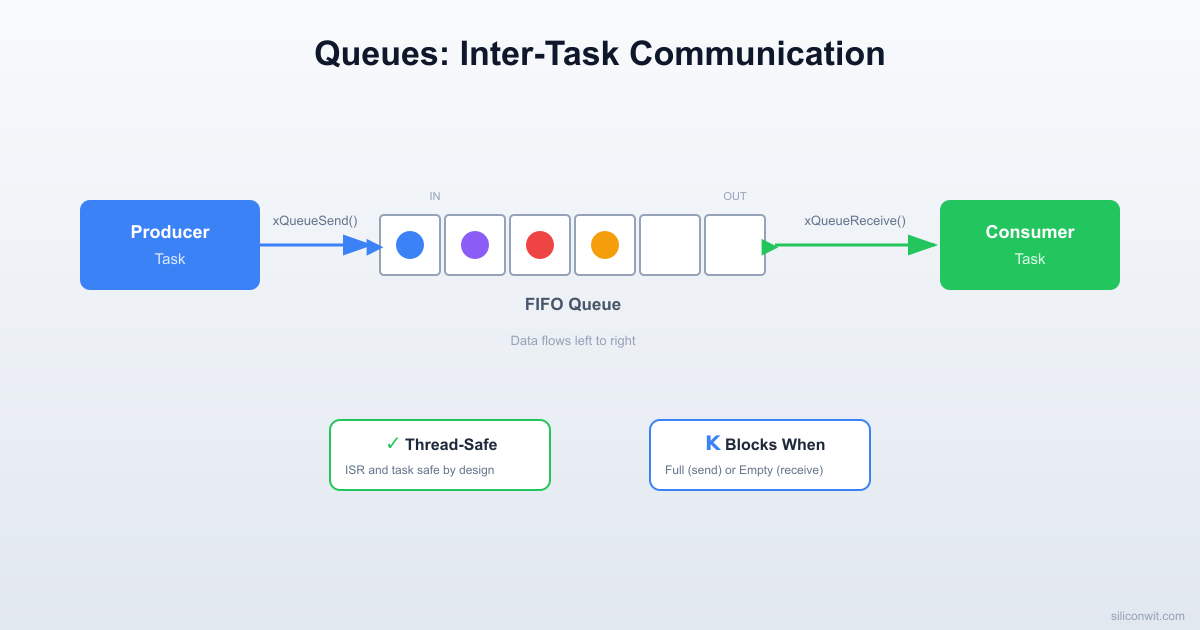
A FreeRTOS queue is a fixed-size FIFO (first in, first out) buffer managed by the kernel. Tasks push items in at one end and pull them out at the other. The kernel handles all synchronization internally, so you never need to disable interrupts or guard access yourself.
Key Properties
Property
Detail
Fixed depth
Set at creation time, cannot be resized
Fixed item size
Every slot holds the same number of bytes
Copy semantics
Data is copied into the queue on send and copied out on receive. The original variable can be reused immediately
Thread-safe
Send and receive are atomic from the caller’s perspective
Blocking
A task can block (sleep) until space is available or data arrives
Creating a Queue
QueueHandle_t xQueue;
/* Create a queue that holds 16 items, each sizeof(uint16_t) bytes */
xQueue =xQueueCreate(16, sizeof(uint16_t));
if (xQueue ==NULL) {
/* Not enough heap memory for the queue */
for (;;); /* Halt or handle error */
}
The xQueueCreate call allocates memory for the queue structure plus depth * item_size bytes of storage from the FreeRTOS heap. If your item is a large struct, consider queuing a pointer instead (but then you must ensure the pointed-to memory stays valid until the receiver reads it).
Sending to a Queue
uint16_t adc_reading =2048;
/* Block forever until space is available */
xQueueSend(xQueue, &adc_reading, portMAX_DELAY);
/* Block for at most 100 ms */
if (xQueueSend(xQueue, &adc_reading, pdMS_TO_TICKS(100)) != pdPASS) {
/* Queue was still full after 100 ms */
missed_samples++;
}
/* Non-blocking: return immediately if full */
if (xQueueSend(xQueue, &adc_reading, 0) != pdPASS) {
/* Queue is full right now */
}
The third parameter is the block time in ticks. Setting it to portMAX_DELAY means the calling task sleeps until a slot opens. Setting it to 0 means try once and return immediately. Any value in between is a timeout.
Receiving from a Queue
uint16_t received_value;
/* Block until data arrives */
if (xQueueReceive(xQueue, &received_value, portMAX_DELAY) == pdPASS) {
/* received_value now contains the oldest item from the queue */
}
xQueueReceive removes the item from the queue. If you want to look at the front item without removing it, use xQueuePeek instead. This is useful when one consumer needs to inspect data before deciding whether to process it.
Producer-Consumer Pattern
The producer-consumer pattern is the most common use of queues. One task generates data, another task processes it, and the queue sits between them as a buffer. Neither task needs to know the other’s timing. If the producer runs faster than the consumer, the queue absorbs bursts. If the consumer runs faster, it simply blocks until more data arrives.
┌──────────┐ ┌──────────┐ ┌──────────┐
│ Producer │───>│ Queue │───>│ Consumer │
│ (ADC) │ │ (FIFO) │ │ (Filter) │
└──────────┘ └──────────┘ └──────────┘
A minimal example:
QueueHandle_t xDataQueue;
voidvProducerTask(void*pvParameters) {
uint16_t value =0;
for (;;) {
value =read_adc(); /* Produce a value */
xQueueSend(xDataQueue, &value, portMAX_DELAY);
vTaskDelay(pdMS_TO_TICKS(10)); /* 100 Hz */
}
}
voidvConsumerTask(void*pvParameters) {
uint16_t received;
for (;;) {
if (xQueueReceive(xDataQueue, &received, portMAX_DELAY)== pdPASS) {
process(received); /* Consume the value */
}
}
}
The consumer has no vTaskDelay because xQueueReceive with portMAX_DELAY already puts the task to sleep when the queue is empty. The task wakes exactly when new data arrives.
  Multi-Stage Pipeline with Queues  ─────────────────────────────────────────  ┌──────────┐ uint16 ┌──────────┐ uint16  │ Producer ├───────►│  Queue   ├───────►  │ (ADC,    │        │ (FIFO,   │  │  100 Hz) │        │  depth=16│  └──────────┘        └──────────┘
  Queue internals:  ┌────┬────┬────┬────┬────┬────┐  │ 12 │ 47 │ 83 │    │    │    │ ◄─ 3 items  └────┴────┴────┴────┴────┴────┘   in queue    ▲ head              tail ▲    (receive)            (send)
Queue Sizing
Choosing the right queue depth is a design decision, not a guess. Too shallow and you lose data during bursts. Too deep and you waste RAM and add latency.
Rules of Thumb
Scenario
Recommended depth
Producer and consumer run at the same average rate
/* Risk: if the consumer is dead, the producer hangs too. */
xQueueSend(xQueue, &val, portMAX_DELAY);
/* Strategy 2: Bounded wait. Producer drops old work after timeout. */
if (xQueueSend(xQueue, &val, pdMS_TO_TICKS(50)) != pdPASS) {
overflow_count++;
/* Log it, skip this sample, or overwrite the oldest item */
}
/* Strategy 3: Non-blocking. Best for ISR contexts or real-time loops. */
if (xQueueSend(xQueue, &val, 0) != pdPASS) {
overflow_count++;
}
For the sensor pipeline in this lesson, we use a depth of 16 with a bounded timeout. If the filter task falls behind by more than 160 ms worth of samples (16 items at 10 ms each), the producer logs a miss and keeps running.
Overwrite Mode
FreeRTOS also provides xQueueOverwrite, which works only on queues of depth 1. It always writes the latest value, overwriting whatever was there. This is useful for “latest value” patterns where you always want the most recent sensor reading and never need history.
Stream Buffers and Message Buffers
Queues are ideal when every item has the same size. For variable-length data, FreeRTOS provides two alternatives introduced in version 10.
Stream Buffers
A stream buffer is a byte-level FIFO, similar to a UART receive ring buffer. It has no concept of discrete messages; the reader pulls however many bytes it wants. This makes stream buffers efficient for forwarding raw byte streams, like UART data from a GPS module or a serial console.
The trigger level sets the minimum number of bytes that must be in the buffer before a blocked reader wakes up. A trigger of 1 means wake on the first byte. A trigger of 64 means wait until at least 64 bytes are available, which reduces context switches for bulk transfers.
Message Buffers
A message buffer wraps a stream buffer but adds a 4-byte length header before each message. This lets you send variable-length messages where the reader always gets one complete message at a time.
Limitation: Stream buffers and message buffers support only one writer and one reader. If you need multiple writers, use a queue or protect access with a mutex.
Event Groups
Sometimes you do not need to pass data between tasks; you just need to signal that something happened. FreeRTOS event groups let multiple tasks set and wait on individual flag bits within a shared 24-bit (or 8-bit on small ports) word.
Creating and Using Event Groups
#include"event_groups.h"
#defineEVT_RAW_DATA_READY (1<<0)
#defineEVT_FILTERED_READY (1<<1)
#defineEVT_DISPLAY_DONE (1<<2)
EventGroupHandle_t xPipelineEvents;
voidsetup_events(void) {
xPipelineEvents =xEventGroupCreate();
}
Setting Bits (Signaling)
/* Producer signals that new raw data is in the queue */
The pdTRUE parameter means the kernel automatically clears the bit after the waiting task unblocks. This prevents stale signals. The pdFALSE parameter means wait for ANY of the specified bits. If you set it to pdTRUE, the task would wait until ALL specified bits are set, which is useful for synchronizing multiple conditions.
Multi-Task Synchronization
Event groups shine when a task must wait for several conditions:
/* Display task waits for BOTH filtered data AND a display-ready signal */
EventBits_t bits =xEventGroupWaitBits(
xPipelineEvents,
EVT_FILTERED_READY | EVT_DISPLAY_DONE,
pdTRUE,
pdTRUE, /* Wait for ALL bits */
pdMS_TO_TICKS(100)
);
Circuit Connections
STM32 Blue Pill Wiring
Signal
Blue Pill Pin
Peripheral
Potentiometer wiper
PA0
ADC1 Channel 0
SSD1306 SDA
PB7
I2C1 SDA
SSD1306 SCL
PB6
I2C1 SCL
SSD1306 VCC
3.3V
Power
SSD1306 GND
GND
Ground
Pot high side
3.3V
Reference
Pot low side
GND
Ground
ESP32 DevKit Wiring
Signal
ESP32 Pin
Peripheral
Potentiometer wiper
GPIO34
ADC1 Channel 6
SSD1306 SDA
GPIO21
I2C SDA
SSD1306 SCL
GPIO22
I2C SCL
SSD1306 VCC
3.3V
Power
SSD1306 GND
GND
Ground
Pot high side
3.3V
Reference
Pot low side
GND
Ground
Connect the potentiometer as a voltage divider: high side to 3.3V, low side to GND, wiper to the ADC pin.
Connect the SSD1306 OLED module: SDA and SCL to the I2C pins, VCC to 3.3V, GND to GND. Most SSD1306 modules have onboard pull-ups, so external pull-ups are optional.
Double-check that both the OLED and potentiometer share a common ground with the microcontroller.
SSD1306 OLED Driver
We need a minimal I2C driver for the SSD1306 to draw a bar graph. This is not a full graphics library; it handles initialization, clearing the display, drawing a filled rectangle (the bar), and writing a single line of text using a basic 5x7 font.
framebuffer[page * SSD1306_WIDTH + x + col] =font5x7[idx][col];
}
x +=6; /* 5 pixels + 1 pixel gap */
str++;
}
}
For a more complete driver (full ASCII font, graphics primitives), the popular ssd1306 library by Aleksei Loginov works well with both STM32 and ESP32. The minimal version above keeps the focus on FreeRTOS queues rather than display code.
Complete Sensor Pipeline
This is the full application. Three tasks communicate through two queues and an event group. The producer reads the ADC at 100 Hz, the filter computes an 8-sample moving average, and the display task renders a bar graph at roughly 20 Hz. Serial output logs queue fill levels so you can see the pipeline in action.
Note the key ESP32 differences: the ESP-IDF provides its own ADC and I2C drivers, stack sizes are larger (ESP32 tasks need at least 2048 bytes), and app_main replaces the bare-metal main because the ESP-IDF scheduler is already running when app_main is called.
The event group bits add an extra signaling layer on top of the queues. The filter task does not spin-poll xQueueReceive; it sleeps until EVT_RAW_READY is set, then drains whatever is available. This keeps CPU usage minimal.
Breaking It: Queue Overflow
The best way to understand queue sizing is to deliberately break the pipeline. Make the filter task artificially slow so the producer fills the raw queue faster than the filter can drain it.
Step 1: Slow Down the Filter
Add a 50 ms delay inside the filter loop so it processes at most 20 samples per second, while the producer pushes 100 per second:
You will see the Q0 (raw queue fill level) climb steadily from 0 toward 16, and the miss counter start incrementing once the queue is full:
ADC:2048 Q0:0 Q1:0 miss:0/0
ADC:2050 Q0:5 Q1:0 miss:0/0
ADC:2047 Q0:10 Q1:0 miss:0/0
ADC:2051 Q0:16 Q1:1 miss:0/0
ADC:2049 Q0:16 Q1:1 miss:3/0
ADC:2052 Q0:16 Q1:1 miss:8/0
Step 3: Fix It
Three approaches, in order of preference:
Fix the root cause. Remove the artificial delay. If the filter is genuinely slow, optimize its algorithm (use a running sum instead of recomputing the entire window each time).
Increase queue depth. If bursts are temporary, a deeper queue absorbs them. But this only delays the problem if the average rate mismatch is permanent.
Throttle the producer. If you cannot speed up the consumer, the producer must slow down or skip samples. Use xQueueSend with a zero timeout and accept that some samples will be dropped.
Project Structure
Directorysensor-pipeline/
Directorysrc/
main.c
ssd1306.c
ssd1306.h
i2c.c
i2c.h
uart.c
uart.h
clock.c
clock.h
Directoryinclude/
FreeRTOSConfig.h
Makefile
platformio.ini
FreeRTOSConfig.h Key Settings
These settings must be enabled for queues, event groups, and the features used in this lesson:
#defineconfigUSE_PREEMPTION1
#defineconfigUSE_EVENT_GROUPS1
#defineconfigSUPPORT_DYNAMIC_ALLOCATION1
#defineconfigTOTAL_HEAP_SIZE ((size_t)(8*1024))
#defineconfigMAX_PRIORITIES5
#defineconfigMINIMAL_STACK_SIZE128
#defineconfigTICK_RATE_HZ1000
The total heap must be large enough for two queues (each QUEUE_DEPTH * sizeof(uint16_t) plus overhead), three task stacks, and the event group. On the Blue Pill with 20 KB of SRAM, 8 KB for the FreeRTOS heap leaves enough room for the SSD1306 framebuffer and other static data.
PlatformIO Configuration
; platformio.ini
[env:bluepill]
platform = ststm32
board = bluepill_f103c8
framework = stm32cube
build_flags =
-DUSE_HAL_DRIVER
-DSTM32F103xB
[env:esp32]
platform = espressif32
board = esp32dev
framework = espidf
Experiments
Add a Second Sensor
Wire a second potentiometer to another ADC channel (PA1 on STM32, GPIO35 on ESP32). Create a second producer task and a second raw queue. Have the filter task pull from both queues and compute independent averages. Display both values as side-by-side bars on the OLED.
Implement Queue Peek
Modify the display task to use xQueuePeek instead of xQueueReceive so it reads the latest filtered value without removing it. Then add a second consumer task that logs data to serial using xQueueReceive. Verify that both consumers see the data.
Stream Buffer for Serial Logging
Replace the direct uart_send_string calls in the display task with writes to a stream buffer. Create a dedicated logging task that drains the stream buffer and sends data over UART. This decouples display rendering from serial I/O, preventing UART blocking from slowing down the display.
Measure Queue Latency
Timestamp each sample in the producer using xTaskGetTickCount and compare it to the tick count when the display task receives it. Log the latency in milliseconds. Vary the queue depth and filter window size, then observe how each parameter affects end-to-end latency.
Comments