A toggle clamp turns a light pull on a handle into a large, self-holding clamping force. The trick is geometry: as the handle approaches top-dead-centre (TDC) the links line up, the mechanical advantage spikes, and a small margin past TDC makes the clamp lock itself with no holding effort. This simulator lets you watch that over-centre action, read the force, transmission angle, pin loads, and stresses at every handle position, and size a real clamp against a material allowable. #ToggleClamp #MechanismSimulator #ForceAnalysis
Mechanical advantage through the full handle travel, with both a rigid (ideal) model that diverges at TDC and an engineering model that includes pin friction and efficiency. See the clamping force the pad delivers for your handle effort.
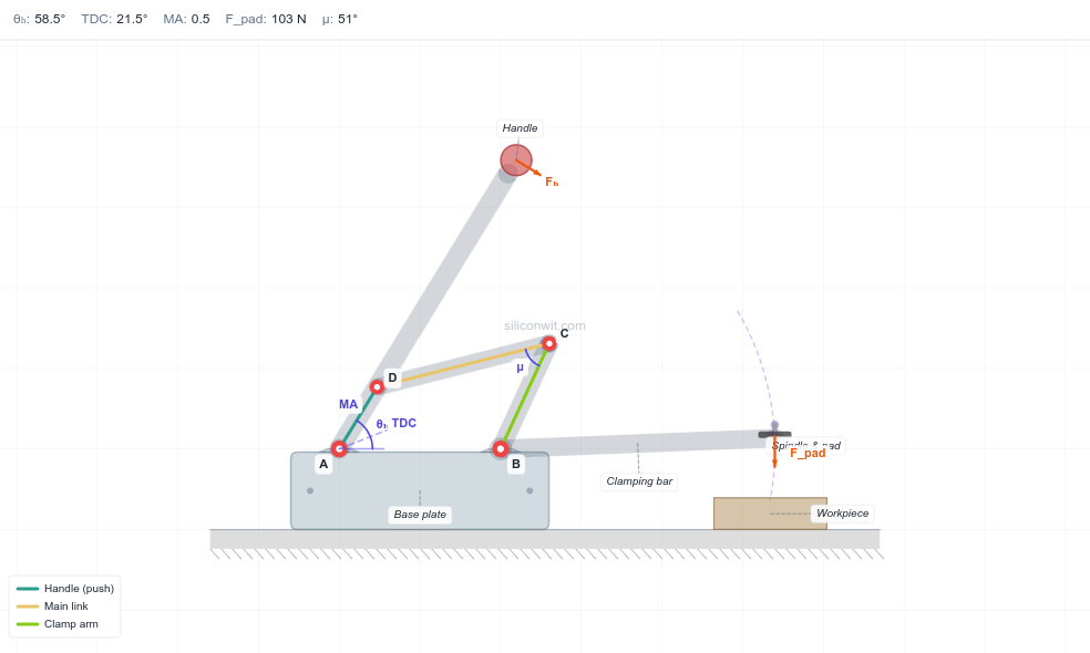
Over-centre lock
Find top-dead-centre numerically, set the lock margin past TDC, and see why the clamp self-locks. The diagram marks TDC, the locked stop, and the current handle angle live.
Transmission angle
Watch the transmission angle at the toggle joint and keep it above the practical 40-degree limit so the linkage transmits force efficiently rather than binding.
Strength and sizing
Pin reactions, link bending stress, and pin shear stress across the travel, with allowable-stress lines from a material yield and safety factor so you can size the pins and links to a Safe or Over-stressed verdict.
Key Features
Over-centre kinematics A real four-bar toggle: handle, main link, and clamp arm, assembled on the hold-down (mirror) circuit so the bar lifts open and presses down at lock.
Two force models A rigid model from the velocity ratio (ideal, diverges at TDC) and an engineering model blending in pin friction and global efficiency for a usable design curve.
Six analysis charts Mechanical advantage, clamping force, transmission angle, pin reactions, link and pin stress, and pad output position, all swept across the handle travel and marked with TDC, lock, and the current angle.
Allowable-stress sizing Enter a material yield strength and safety factor; the stress chart draws the bending and shear allowables and the panel reports a Safe or Over-stressed verdict.
Five size-class presets From a mini benchtop clamp to a heavy industrial fixture, each a feasible, distinct configuration.
Live A/B comparison Save Experiment A, change parameters, and overlay run B on every chart to compare two designs directly.
Downloadable resources A design-data sheet, the full analysis dataset as CSV (both experiments when you compare two), and a complete lab report with watermark-free diagram, charts, and animation.
Preset Configurations
Preset
Handle Lh (mm)
Base spacing d (mm)
Pad reach (mm)
Handle force (N)
Class
Mini benchtop
18
38
70
50
Small bench tool
Light-duty vertical
28
58
95
80
Light hold-down
Medium-duty vertical
40
70
110
120
General fixture
Heavy-duty vertical
45
100
170
200
Heavy hold-down
Industrial
65
140
240
250
Large fixture
Equations
Rigid (ideal) mechanical advantage from the four-bar velocity ratio and the handle lever:
Comments