//! Potentiometer-controlled servo with buzzer feedback on the Raspberry Pi Pico.
//! GP0 (PWM0A): Servo signal (50 Hz, 0.5-2.5 ms pulse)
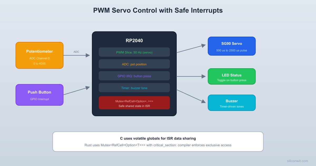
//! GP18 (GPIO): Piezo buzzer (toggled by timer interrupt)
//! GP26 (ADC0): Potentiometer wiper
//! The potentiometer sets the servo angle (0-180 degrees).
//! The buzzer plays a tone proportional to the angle:
//! 0 degrees -> 200 Hz, 180 degrees -> 2000 Hz.
//! The buzzer frequency is generated by a timer alarm interrupt
//! that toggles the buzzer GPIO at the required half-period.
use critical_section::Mutex;
use rp_pico::hal::pac::interrupt;
use embedded_hal::digital::{OutputPin, StatefulOutputPin};
use embedded_hal::delay::DelayNs;
use embedded_hal::pwm::SetDutyCycle;
use embedded_hal_0_2::adc::OneShot;
// ================================================================
// Shared state between main loop and TIMER_IRQ_0 interrupt handler
// ================================================================
/// The raw TIMER peripheral, moved into the ISR via Option.
static TIMER_PERIPH: Mutex<RefCell<Option<pac::TIMER>>> =
Mutex::new(RefCell::new(None));
/// Buzzer half-period in microseconds. 0 means buzzer off.
/// Updated by main loop, read by ISR.
static BUZZER_HALF_PERIOD_US: Mutex<RefCell<u32>> =
Mutex::new(RefCell::new(0));
/// Buzzer GPIO pin, moved into the ISR via Option.
/// Using the specific pin type for GP18 configured as push-pull output.
type BuzzerPin = hal::gpio::Pin<
hal::gpio::bank0::Gpio18,
hal::gpio::FunctionSio<hal::gpio::SioOutput>,
static BUZZER_PIN: Mutex<RefCell<Option<BuzzerPin>>> =
Mutex::new(RefCell::new(None));
// ================================================================
// Timer interrupt handler: toggles buzzer at the configured frequency
// ================================================================
critical_section::with(|cs| {
let mut timer_ref = TIMER_PERIPH.borrow_ref_mut(cs);
let half_period = *BUZZER_HALF_PERIOD_US.borrow_ref(cs);
if let Some(ref timer) = *timer_ref {
// Clear the alarm 0 interrupt flag
timer.intr().write(|w| w.alarm_0().clear_bit_by_one());
let mut pin_ref = BUZZER_PIN.borrow_ref_mut(cs);
if let Some(ref mut pin) = *pin_ref {
if pin.is_set_high().unwrap_or(false) {
// Schedule the next alarm
let now = timer.timerawl().read().bits();
let next = now.wrapping_add(half_period);
timer.alarm0().write(|w| unsafe { w.bits(next) });
// ================================================================
// ================================================================
/// Map a 12-bit ADC value (0-4095) to a servo angle (0-180).
fn adc_to_angle(adc_val: u16) -> u16 {
((adc_val as u32 * 180) / 4095) as u16
/// Map a servo angle (0-180) to a PWM compare value for the servo.
/// Servo expects 0.5 ms to 2.5 ms pulse in a 20 ms period.
/// With PSC such that counter runs at 1 MHz and wrap = 19999:
/// 0 degrees -> 500 (0.5 ms)
/// 90 degrees -> 1500 (1.5 ms)
/// 180 degrees -> 2500 (2.5 ms)
fn angle_to_servo_duty(angle: u16) -> u16 {
let angle = if angle > 180 { 180 } else { angle };
500 + ((angle as u32 * 2000) / 180) as u16
/// Map a servo angle (0-180) to a buzzer frequency (200-2000 Hz).
/// Returns the half-period in microseconds for the timer interrupt.
/// Returns 0 if angle is 0 (buzzer off at minimum).
fn angle_to_buzzer_half_period(angle: u16) -> u32 {
// Frequency: 200 Hz at 0 degrees, 2000 Hz at 180 degrees
let freq_hz = 200 + ((angle as u32 * 1800) / 180);
// Half-period in microseconds: 1_000_000 / (2 * freq_hz)
1_000_000 / (2 * freq_hz)
// ================================================================
// ================================================================
defmt::info!("Booting rp2040-servo-buzzer");
// ---- Peripheral setup ----
let mut pac = pac::Peripherals::take().unwrap();
let core = pac::CorePeripherals::take().unwrap();
let mut watchdog = hal::Watchdog::new(pac.WATCHDOG);
let clocks = hal::clocks::init_clocks_and_plls(
rp_pico::XOSC_CRYSTAL_FREQ,
clocks.system_clock.freq().to_MHz()
let sio = hal::Sio::new(pac.SIO);
let pins = rp_pico::Pins::new(
// ---- PWM setup for servo (GP0, slice 0, channel A) ----
let pwm_slices = hal::pwm::Slices::new(pac.PWM, &mut pac.RESETS);
let mut pwm0 = pwm_slices.pwm0;
// Configure for 50 Hz: 125 MHz / 125 = 1 MHz counter, wrap at 19999
let channel_a = &mut pwm0.channel_a;
channel_a.output_to(pins.gpio0);
// Start at center (90 degrees = 1500 us pulse)
channel_a.set_duty_cycle(1500).unwrap();
defmt::info!("Servo PWM configured: 50 Hz on GP0");
// ---- Buzzer GPIO setup (GP18 as push-pull output) ----
let buzzer_pin = pins.gpio18.into_push_pull_output();
// Move the buzzer pin into the static for ISR access
critical_section::with(|cs| {
BUZZER_PIN.borrow_ref_mut(cs).replace(buzzer_pin);
// ---- ADC setup (GP26 = ADC0 for potentiometer) ----
let mut adc = hal::Adc::new(pac.ADC, &mut pac.RESETS);
let mut adc_pin = hal::adc::AdcPin::new(pins.gpio26).unwrap();
defmt::info!("ADC configured on GP26");
// ---- Timer alarm setup for buzzer interrupt ----
// We need the raw TIMER peripheral for alarm interrupts.
// The HAL Timer type does not expose alarm interrupts directly
// in a way that works cleanly with the static Mutex pattern,
// so we use the PAC directly for the alarm.
// Note: pac.TIMER was already used by hal::Timer if we created one.
// Instead, we access it through the Mutex after moving it there.
// Enable alarm 0 interrupt in the TIMER peripheral
// We need to configure this before moving the peripheral
timer.inte().modify(|_, w| w.alarm_0().set_bit());
// Set an initial alarm (will be reconfigured by the ISR)
let initial_alarm = timer.timerawl().read().bits().wrapping_add(100_000);
timer.alarm0().write(|w| unsafe { w.bits(initial_alarm) });
// Move the TIMER peripheral into the static for ISR access
critical_section::with(|cs| {
TIMER_PERIPH.borrow_ref_mut(cs).replace(timer);
// Enable the TIMER_IRQ_0 interrupt in the NVIC
pac::NVIC::unmask(pac::Interrupt::TIMER_IRQ_0);
defmt::info!("Timer alarm 0 interrupt enabled for buzzer");
// ---- Create a SysTick-based delay for the main loop ----
let mut delay = cortex_m::delay::Delay::new(
clocks.system_clock.freq().to_Hz(),
let mut last_angle: u16 = 255; // impossible value to force first update
defmt::info!("Entering main loop. Turn the potentiometer.");
// Read the potentiometer (12-bit: 0 to 4095)
let adc_value: u16 = adc.read(&mut adc_pin).unwrap();
// Map to servo angle (0 to 180 degrees)
let angle = adc_to_angle(adc_value);
// Only update if the angle changed (reduces servo jitter)
// Update servo PWM duty cycle
let duty = angle_to_servo_duty(angle);
pwm0.channel_a.set_duty_cycle(duty).unwrap();
// Update buzzer frequency via the shared Mutex
let half_period = angle_to_buzzer_half_period(angle);
critical_section::with(|cs| {
*BUZZER_HALF_PERIOD_US.borrow_ref_mut(cs) = half_period;
"ADC: {} | Angle: {} deg | Servo duty: {} | Buzzer half-period: {} us",
// Small delay to avoid flooding the ADC and RTT
Comments