Plug a Raspberry Pi Pico into any computer and it types a message for you, no drivers, no serial monitor, no special software. The Pico enumerates as a USB HID keyboard and sends keystrokes automatically. Building this tiny project will teach you everything about the RP2040 boot process, the Pico SDK toolchain, and the CMake build system that ties it all together. #PicoSDK #RP2040 #EmbeddedSystems
What We Are Building
USB Text Injector
A Raspberry Pi Pico programmed to appear as a USB keyboard. When plugged into any computer, it waits briefly, then types a predefined text string one character at a time. No drivers or software needed on the host. This demonstrates UF2 flashing, the TinyUSB HID stack, and the complete SDK build pipeline.
Set the environment variable permanently through System Properties, or in the current session:
Terminal window
setPICO_SDK_PATH=%USERPROFILE%\pico-sdk
setxPICO_SDK_PATH%USERPROFILE%\pico-sdk
Verify the toolchain:
Terminal window
arm-none-eabi-gcc--version
cmake--version
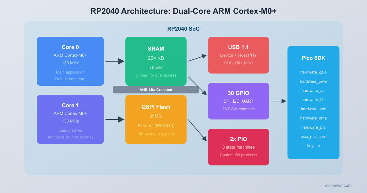
RP2040 Architecture
The RP2040 is the microcontroller at the heart of the Raspberry Pi Pico. Understanding its architecture helps you write better firmware and debug problems that would otherwise seem mysterious.
RP2040 Block Diagram
┌─────────────────────────────────────────┐
│ ┌──────────┐ ┌──────────┐ │
│ │ Cortex-M0+│ │ Cortex-M0+│ │
│ │ Core 0 │ │ Core 1 │ │
│ │ 133 MHz │ │ 133 MHz │ │
│ └─────┬─────┘ └─────┬─────┘ │
│ └──────────┬─────────┘ │
│ ┌──────┴──────┐ │
│ │ Bus Fabric │ │
│ │ (AHB-Lite) │ │
│ └──┬───┬───┬──┘ │
│ ┌───────┐ │ │ │ ┌───────────┐ │
│ │ SRAM │──┘ │ └──│ PIO x2 │ │
│ │ 264KB │ │ │ 8 machines│ │
│ │ 6 banks│ │ └───────────┘ │
│ └───────┘ ┌───┴────┐ ┌───────────┐ │
│ ┌───────┐ │ DMA │ │ USB 1.1 │ │
│ │ Flash │ │ 12 ch │ │ PHY │ │
│ │ QSPI │ └────────┘ └───────────┘ │
│ └───────┘ │
└─────────────────────────────────────────┘
Dual Cortex-M0+ Cores
The RP2040 contains two ARM Cortex-M0+ processor cores running at up to 133 MHz. Both cores share the same address space, meaning they can access the same peripherals and memory. Core 0 is the default execution core. Core 1 starts in a sleep state and can be launched from firmware using the multicore_launch_core1() SDK function. Each core has its own stack pointer and can run independent code, but they share all peripheral registers and SRAM.
The Cortex-M0+ is the smallest ARM core with a Thumb-2 instruction set. It has a two-stage pipeline, single-cycle I/O port access, and a hardware multiplier. There is no floating-point unit, so all floating-point operations are emulated in software.
Memory: 264 KB SRAM in 6 Banks
The RP2040 has 264 KB of on-chip SRAM divided into six banks:
Bank
Size
Address Range
Bank 0
64 KB
0x20000000 to 0x2000FFFF
Bank 1
64 KB
0x20010000 to 0x2001FFFF
Bank 2
64 KB
0x20020000 to 0x2002FFFF
Bank 3
64 KB
0x20030000 to 0x2003FFFF
Bank 4
4 KB
0x20040000 to 0x20040FFF
Bank 5
4 KB
0x20041000 to 0x20041FFF
Banks 0 through 3 are striped: consecutive 32-bit words go to different banks. This means both cores and DMA can often access SRAM simultaneously without stalling, because their accesses hit different banks. Banks 4 and 5 are smaller and often used for the core 0 and core 1 stacks.
Bus Fabric (AHB-Lite Crossbar)
The bus fabric is the interconnect that routes data between masters (both CPU cores and DMA) and slaves (SRAM banks, peripherals, and flash). It is a full crossbar, meaning multiple masters can access different slaves at the same time without conflict. If two masters try to access the same slave in the same cycle, the arbiter grants one and stalls the other.
This crossbar design is what makes the dual-core architecture practical. Core 0 can read from SRAM bank 0 while core 1 writes to SRAM bank 2 and DMA transfers data from a peripheral to SRAM bank 1, all in the same clock cycle.
Boot Process
The RP2040 boot sequence has three stages:
ROM Bootloader (on-chip): The RP2040 has a 16 KB mask ROM at address 0x00000000. On power-up, the chip always starts executing from this ROM. The ROM bootloader checks the external flash for a valid second-stage boot header. If the BOOTSEL button is held during reset (or no valid flash image is found), the ROM enumerates as a USB mass storage device, ready to accept a UF2 file.
Second-Stage Boot (in flash): The first 256 bytes of external flash contain a second-stage bootloader. This small program configures the flash chip for XIP (Execute In Place) mode, setting up the correct SPI clock speed and read commands. The Pico SDK provides this bootloader automatically.
Application Entry: Once XIP is configured, the processor reads the vector table from flash and jumps to the reset handler, which is your main() function after the SDK runtime initialization runs.
The UF2 (USB Flashing Format) file format is what makes the drag-and-drop programming possible. When the Pico appears as a USB drive, you simply copy the .uf2 file to it. The ROM bootloader writes each UF2 block to the correct flash address and reboots.
Project Structure
Create a project directory with the following layout:
Directoryusb-text-injector/
CMakeLists.txt
main.c
tusb_config.h
usb_descriptors.c
pico_sdk_import.cmake
Directorybuild/
…
The pico_sdk_import.cmake file is a helper script that locates the Pico SDK using the PICO_SDK_PATH environment variable. Copy it from the SDK:
Terminal window
cp$PICO_SDK_PATH/external/pico_sdk_import.cmake.
CMakeLists.txt
CMake is the build system used by the Pico SDK. The CMakeLists.txt file defines your project, tells CMake where to find the SDK, and specifies which libraries to link. Here is the minimum configuration for a TinyUSB HID project:
cmake_minimum_required(VERSION 3.13)
# Pull in the Pico SDK (must come before project())
include(pico_sdk_import.cmake)
project(usb_text_injector C CXX ASM)
set(CMAKE_C_STANDARD 11)
set(CMAKE_CXX_STANDARD 17)
# Initialize the SDK
pico_sdk_init()
add_executable(usb_text_injector
main.c
usb_descriptors.c
)
# Link the TinyUSB device library and standard SDK libraries
pico_sdk_init() must be called after project() but before any target definitions.
tinyusb_device and tinyusb_board are SDK libraries that provide the full TinyUSB stack compiled for the RP2040.
pico_add_extra_outputs() generates .uf2, .bin, and .dis (disassembly) files in addition to the .elf.
UF2 Flashing
UF2 Boot and Flash Process
┌────────────┐ Hold BOOTSEL ┌────────────┐
│ Pico │ + plug USB │ Pico │
│ (running) ├────────────────>│ BOOTSEL │
└────────────┘ │ (USB MSC) │
└─────┬──────┘
│
┌──────────────────┘
v
┌──────────────┐ ┌────────────┐
│ RPI-RP2 │ │ Pico │
│ USB Drive │───>│ Flashes │
│ Copy .uf2 │ │ & Reboots │
└──────────────┘ └────────────┘
Drag & drop Runs your
firmware.uf2 application
The Raspberry Pi Pico uses a simple drag-and-drop method for programming:
Unplug the Pico from USB.
Hold down the BOOTSEL button (the white button on the board).
While holding BOOTSEL, plug the Pico into your computer via USB.
Release BOOTSEL. The Pico appears as a USB mass storage device named RPI-RP2.
Drag (or copy) the .uf2 file onto the RPI-RP2 drive.
The Pico automatically flashes the firmware, unmounts the drive, and reboots into your application.
On Linux, the drive typically mounts under /media/$USER/RPI-RP2. On macOS it appears on the desktop and in /Volumes/RPI-RP2. On Windows it shows up as a new drive letter in File Explorer.
TinyUSB HID Keyboard Configuration
TinyUSB is the USB stack included with the Pico SDK. To make the Pico appear as a USB HID keyboard, you need two configuration files: tusb_config.h and usb_descriptors.c.
tusb_config.h
This header tells TinyUSB what kind of device to build. The key settings are the device class (HID), the endpoint buffer size, and the report descriptor length.
#ifndefTUSB_CONFIG_H
#defineTUSB_CONFIG_H
/* Board and MCU configuration (RP2040) */
#defineCFG_TUSB_MCU OPT_MCU_RP2040
#defineCFG_TUSB_OS OPT_OS_PICO
/* USB device configuration */
#defineCFG_TUD_ENABLED1
#defineCFG_TUD_HID1
#defineCFG_TUD_CDC0
#defineCFG_TUD_MSC0
#defineCFG_TUD_MIDI0
#defineCFG_TUD_VENDOR0
/* HID buffer size */
#defineCFG_TUD_HID_EP_BUFSIZE16
#endif /* TUSB_CONFIG_H */
usb_descriptors.c
The USB descriptor file defines the device identity (VID/PID, manufacturer string, product string) and the HID report descriptor that tells the host OS what kind of input the device produces. The report descriptor below defines a standard keyboard with modifier keys and six simultaneous key slots.
The main firmware waits for USB enumeration to complete, pauses for one second so the host OS finishes loading the HID driver, and then types out a predefined message one character at a time. Each character is converted to the corresponding HID keycode, sent as a key-press report, then released with an empty report. The delay between keystrokes keeps the output readable.
#include<stdlib.h>
#include<stdio.h>
#include<string.h>
#include"pico/stdlib.h"
#include"bsp/board.h"
#include"tusb.h"
/* Message to type when plugged in */
staticconstchar*MESSAGE ="Hello from Raspberry Pi Pico!\n";
/* Convert an ASCII character to HID keycode and modifier */
/* Give the host OS time to load the HID driver */
sleep_ms(1000);
/* Type the message */
type_string(MESSAGE);
/* Keep USB alive (required by TinyUSB) */
while (1) {
tud_task();
sleep_ms(100);
}
return0;
}
How It Works
The firmware follows a straightforward sequence:
board_init() configures the Pico’s clocks, GPIO, and on-board LED.
tusb_init() initializes the TinyUSB stack and starts USB enumeration. The host PC sees a new HID keyboard device.
The main loop polls tud_task() until tud_mounted() returns true, meaning the host has accepted the device.
After a 1-second delay, type_string() iterates through each character of the message. For each character, char_to_keycode() maps it to a USB HID keycode (and shift modifier if needed), and send_key() transmits a press report followed by a release report.
After typing finishes, the firmware continues calling tud_task() in an infinite loop. This keeps the USB connection alive so the host does not report a device disconnect.
The 15 ms delay between press and release, plus the 50 ms delay between characters, produces clean output at roughly 12 characters per second. If you reduce these delays too much, some operating systems may drop keystrokes.
Building and Flashing
Create the build directory and run CMake:
Terminal window
cdusb-text-injector
mkdirbuild && cdbuild
cmake..
Compile the project:
Terminal window
make-j$(nproc)
This produces usb_text_injector.uf2 in the build directory. The output also shows flash and RAM usage.
Put the Pico into BOOTSEL mode: unplug it, hold the BOOTSEL button, plug it back in, then release the button.
Copy the UF2 file to the Pico:
Terminal window
# Linux
cpusb_text_injector.uf2/media/$USER/RPI-RP2/
# macOS
cpusb_text_injector.uf2/Volumes/RPI-RP2/
# Windows (adjust drive letter)
copyusb_text_injector.uf2E:\
The Pico reboots, enumerates as a keyboard, waits one second, and types the message into whatever application has focus.
Exercises
Modify the MESSAGE string to type your full name, email address, and a greeting on separate lines. Verify that special characters (periods, at-signs, colons) are handled correctly, and add any missing keycode mappings.
Add an on-board LED blink after each character is typed. Use gpio_put(PICO_DEFAULT_LED_PIN, 1) and gpio_put(PICO_DEFAULT_LED_PIN, 0) with a short delay. This gives visual feedback during typing.
Make the Pico wait for a button press before typing. Connect a tactile button between GP14 and GND, enable the internal pull-up with gpio_pull_up(), and only call type_string() when the button is pressed. This prevents accidental typing on every plug-in.
Extend the firmware to type the message repeatedly with a 5-second pause between cycles. Add a cycle counter and stop after 3 repetitions, then turn on the LED to indicate completion.
Summary
You installed the Pico C SDK, learned how the RP2040’s dual Cortex-M0+ cores share 264 KB of banked SRAM through an AHB-Lite crossbar, and traced the three-stage boot process from mask ROM through XIP flash to your application. The CMake build system compiles your code, links the SDK libraries, and produces a UF2 file that you drag onto the Pico. The USB text injector project demonstrated the TinyUSB HID stack, descriptor configuration, and keycode mapping. Every lesson in this course builds on this same SDK setup, CMake workflow, and UF2 flash process.
Comments