On a microcontroller, you configure peripherals by writing directly to hardware registers. On embedded Linux, the kernel needs a structured description of what hardware exists, where it is mapped in memory, and which driver should manage it. That description lives in device tree files. In this lesson, you will read the base device tree for the BCM2710, understand how nodes, properties, and phandles work, and then write your own overlay that enables a BME280 sensor on I2C bus 1. After loading the overlay, the sensor appears automatically in the kernel’s IIO subsystem, ready for userspace applications to read. #DeviceTree #I2C #EmbeddedLinux
What We Are Building
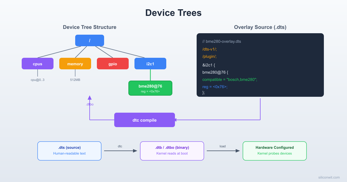
Custom Device Tree Overlay for BME280 Sensor
A device tree overlay (.dtbo) that declares a Bosch BME280 environmental sensor at address 0x76 on the I2C1 bus of the Raspberry Pi Zero 2 W. When the overlay is loaded at boot, the kernel instantiates the bme280 IIO driver automatically. You can then read temperature, humidity, and pressure values from sysfs without writing a single line of driver code.
Project specifications:
Parameter
Value
Overlay target
I2C1 bus (GPIO2 = SDA, GPIO3 = SCL)
Sensor
Bosch BME280 (temperature, humidity, pressure)
I2C address
0x76 (default with SDO tied to GND)
Kernel driver
bme280 (IIO subsystem)
Overlay format
.dtbo compiled from .dts source
Loading method
config.txt dtoverlay= directive
Verification
sysfs IIO readings + i2cdetect confirmation
Tools
dtc (device tree compiler), i2c-tools
Bill of Materials
Ref
Component
Quantity
Notes
1
BME280 breakout module
1
Reuse from prior courses; I2C mode
2
Jumper wires (female-female)
4
SDA, SCL, VCC (3.3V), GND
What is a Device Tree?
On a bare-metal microcontroller like the ATmega328P, you know exactly what hardware is available because you wrote the code to talk to specific registers at specific addresses. The chip’s datasheet tells you that PORTB lives at address 0x25, TWBR at 0xB8, and so on. Your firmware is compiled for one specific chip, so the addresses are hardcoded.
Linux kernels, however, run on hundreds of different boards. The same ARM kernel image can boot on a Raspberry Pi, a BeagleBone, or a custom industrial board. Each board has different peripherals wired in different ways. The kernel cannot hardcode all of these configurations. It needs a data structure, passed in at boot time, that says: “This board has 4 CPUs starting at address 0x0. It has an I2C controller at address 0x7e804000. GPIO pin 2 and pin 3 are assigned to that I2C controller.”
That data structure is the device tree.
Without Device Trees
Every board needs a custom-compiled kernel with hardware details baked into C source files. Adding a new board means modifying kernel code, recompiling, and maintaining a fork.
With Device Trees
One kernel binary works across many boards. Hardware details live in a separate .dtb file that the bootloader passes to the kernel. Adding a new board means writing a new .dts text file and compiling it.
Device Tree: Base + Overlay
──────────────────────────────────────────
bcm2710-rpi-zero-2-w.dts (base, from SoC)
┌───────────────────────────────┐
│ / { │
│ cpus { cpu@0 { ... }; }; │
│ soc { │
│ i2c1: i2c@7e804000 { │
│ status = "disabled"; │
│ }; │
│ }; │
│ }; │
└───────────────────────────────┘
+
my-overlay.dts (your overlay)
┌───────────────────────────────┐
│ &i2c1 { │
│ status = "okay"; │
│ bme280@76 { │
│ compatible = "bosch,..."; │
│ reg = <0x76>; │
│ }; │
│ }; │
└───────────────────────────────┘
=
Final merged tree at boot
The device tree originated in Open Firmware (IEEE 1275) and was adopted by the Linux ARM community around 2011 to replace the explosion of board-specific C files in arch/arm/mach-*.
Key Terminology
Term
Meaning
DTS
Device Tree Source, the human-readable text file (.dts)
DTB
Device Tree Blob, the compiled binary (.dtb)
DTBO
Device Tree Blob Overlay, a compiled overlay fragment (.dtbo)
DTC
Device Tree Compiler, the tool that converts DTS to DTB
Node
A block in the tree representing a device or bus
Property
A key-value pair inside a node (e.g., compatible = "bosch,bme280")
Phandle
A numeric reference that lets one node point to another
DTS Compilation and Loading
──────────────────────────────────────────
my-overlay.dts (text, you edit this)
│
▼
dtc -I dts -O dtb -o my-overlay.dtbo
│
▼
my-overlay.dtbo (binary, kernel reads this)
│
│ config.txt: dtoverlay=my-overlay
▼
Bootloader merges overlay with base DTB
│
▼
Kernel sees merged tree at /proc/device-tree
DTS Syntax Primer
A device tree source file is a text file with a tree structure. Every DTS file starts with a version tag and a root node.
Minimal Example
/dts-v1/;
/ {
model = "Minimal Example Board";
compatible = "example,minimal";
memory@0 {
device_type = "memory";
reg = <0x0 0x20000000>;
};
leds {
compatible = "gpio-leds";
status_led: led0 {
label = "status";
gpios = <&gpio 27 0>;
default-state = "off";
};
};
};
Let’s break down the syntax rules:
Version Tag
/dts-v1/;
This must be the first line. It tells the compiler you are using the current DTS syntax (version 1). Without it, the compiler assumes the legacy format.
Root Node
/ {
...
};
The forward slash represents the root of the tree. Every device tree has exactly one root node. All other nodes are children (or descendants) of this root.
Child Nodes
Nodes are defined with a name and optional unit address:
memory@0 {
...
};
The @0 is the unit address, which typically matches the first value in the reg property. It disambiguates nodes with the same base name (e.g., uart@7e201000 vs uart@7e215040).
Properties
Properties are key-value pairs inside a node. The value can be several types:
/* String */
compatible = "bosch,bme280";
/* String list */
compatible = "vendor,specific", "vendor,generic";
/* 32-bit integer cells (in angle brackets) */
reg = <0x7e804000 0x1000>;
/* Byte string */
local-mac-address = [00 11 22 33 44 55];
/* Empty (boolean: property exists = true) */
status = "okay";
The compatible Property
This is the most important property. The kernel uses it to match a device node to the correct driver. The format is "manufacturer,device":
compatible = "bosch,bme280";
When the kernel encounters this node, it searches its driver database for a driver that lists "bosch,bme280" in its of_match_table. If found, the kernel binds that driver to this device.
The reg Property
Describes the address range(s) of the device:
reg = <address length>;
For an I2C device, reg is simply the I2C slave address:
reg = <0x76>;
For a memory-mapped peripheral, it includes the base address and size:
reg = <0x7e804000 0x1000>;
The status Property
Controls whether the kernel activates a device:
Value
Meaning
"okay"
Device is present and should be enabled
"disabled"
Device exists but should not be activated
Many nodes in the base device tree are set to "disabled" by default. An overlay sets them to "okay" when the hardware is actually connected.
Labels and Phandles
A label is a shorthand name placed before a node:
gpio: gpio@7e200000 {
...
#gpio-cells = <2>;
};
Other nodes reference this label with &gpio:
gpios = <&gpio 27 0>;
The compiler converts the label reference into a numeric phandle in the compiled DTB. You never need to assign phandle numbers manually.
Reading the Base Device Tree
The Raspberry Pi Zero 2 W uses the BCM2710A1 SoC. The base device tree source lives in the Linux kernel source tree:
Notice that status = "disabled". The base tree ships I2C1 as disabled. The Raspberry Pi firmware’s config.txt option dtparam=i2c_arm=on loads an overlay that changes this to "okay".
SPI0 bus:
spi0: spi@7e204000 {
compatible = "brcm,bcm2835-spi";
reg = <0x7e204000 0x200>;
clocks = <&clocks BCM2835_CLOCK_VPU>;
#address-cells = <1>;
#size-cells = <0>;
status = "disabled";
};
How the Bootloader Merges Overlays
The Raspberry Pi boot process works as follows:
The GPU firmware reads config.txt from the boot partition.
It loads the base DTB file (e.g., bcm2710-rpi-zero-2-w.dtb) into memory.
For each dtoverlay= line in config.txt, it loads the corresponding .dtbo file from /boot/overlays/.
It merges each overlay into the base tree in order, modifying or adding nodes.
The final merged device tree is passed to the kernel at the address specified in register x0 (AArch64) or r2 (AArch32).
The kernel parses the tree and instantiates drivers for every node with status = "okay".
This means you never modify the base DTB directly. You write small overlay files that patch specific parts of the tree.
Device Tree Compiler (dtc)
The device tree compiler (dtc) converts between DTS (text) and DTB (binary) formats. Install it on your development machine or directly on the Pi:
For an overlay (use the -@ flag to preserve symbols for phandle resolution):
Terminal window
dtc-@-Idts-Odtb-ooverlay.dtbooverlay.dts
The -@ flag tells the compiler to generate a __symbols__ node, which the bootloader needs to resolve label references like &i2c1 against the base tree.
Decompile DTB to DTS
This is invaluable for inspecting what is actually loaded on a running system:
Now let’s write a device tree overlay that tells the kernel: “There is a Bosch BME280 sensor at I2C address 0x76 on the I2C1 bus.”
Create a file called bme280-sensor.dts:
bme280-sensor.dts
/dts-v1/;
/plugin/;
/ {
compatible = "brcm,bcm2835";
fragment@0 {
target = <&i2c1>;
__overlay__ {
#address-cells = <1>;
#size-cells = <0>;
status = "okay";
bme280: bme280@76 {
compatible = "bosch,bme280";
reg = <0x76>;
status = "okay";
};
};
};
};
Let’s examine every line:
/dts-v1/;: Required version tag.
/plugin/;: Marks this file as an overlay (not a standalone device tree). This tells the compiler that unresolved references like &i2c1 are expected and will be resolved against the base tree at boot time.
compatible = "brcm,bcm2835";: Declares which base device tree this overlay is compatible with. The BCM2710 (Pi Zero 2 W) is backward-compatible with BCM2835.
fragment@0: An overlay can contain multiple fragments. Each fragment targets a specific node in the base tree.
target = <&i2c1>;: This fragment’s changes will be applied to the i2c1 node in the base tree. The &i2c1 reference resolves to the phandle of the I2C1 controller node.
__overlay__ { ... }: Everything inside this block gets merged into the target node. Properties listed here override existing properties in the target. New child nodes are added.
#address-cells = <1>; and #size-cells = <0>;: These tell the device tree parser that child nodes of this bus have 1-cell addresses (the I2C slave address) and no size component.
status = "okay";: Enables the I2C1 bus itself (overriding the base tree’s "disabled").
bme280@76: A child node representing the sensor. The @76 is the unit address matching reg.
compatible = "bosch,bme280";: The kernel’s BME280 IIO driver registers itself for this compatible string. When the kernel sees this node, it loads the bme280 driver module.
reg = <0x76>;: The I2C slave address. If you have connected the SDO pin of your BME280 module to VCC, use <0x77> instead.
A temperature reading of 23450 means 23.45 degrees Celsius.
If the IIO device does not appear, check dmesg for errors:
Terminal window
dmesg|grep-ibme
dmesg|grep-ii2c
Common issues include: the BME280 module not being wired correctly, the I2C bus not being enabled, or the kernel not having the bme280 IIO driver built in (it may need to be loaded as a module with sudo modprobe bme280).
Pin Multiplexing (pinctrl)
Most SoC pins can serve multiple functions. GPIO2 and GPIO3 on the BCM2710 can be general-purpose I/O pins, or they can serve as the SDA1 and SCL1 lines for the I2C1 controller. The decision about which function a pin performs is called pin multiplexing, and the subsystem that manages it in the device tree is called pinctrl.
How I2C1 Pins Are Configured in the Base DTS
In the BCM2835 base device tree, the pin configuration for I2C1 is defined in the GPIO node:
gpio: gpio@7e200000 {
compatible = "brcm,bcm2835-gpio";
/* ... */
i2c1_pins: i2c1 {
brcm,pins = <2 3>;
brcm,function = <4>; /* ALT0 = I2C1 SDA/SCL */
};
};
The brcm,pins property lists GPIO2 and GPIO3. The brcm,function value 4 corresponds to ALT0, which maps these pins to the I2C1 peripheral.
The I2C1 node then references this pin configuration:
i2c1: i2c@7e804000 {
compatible = "brcm,bcm2835-i2c";
reg = <0x7e804000 0x1000>;
pinctrl-names = "default";
pinctrl-0 = <&i2c1_pins>;
/* ... */
};
The pinctrl-0 = <&i2c1_pins> line tells the kernel: “When this device is active, configure the pins as specified in the i2c1_pins node.”
Adding pinctrl to a Custom Overlay
If you are creating an overlay for a peripheral that needs specific pin assignments, you can include a pinctrl node in your overlay. Here is an example that defines a custom pin configuration for SPI0 and references it:
/dts-v1/;
/plugin/;
/ {
compatible = "brcm,bcm2835";
fragment@0 {
target = <&gpio>;
__overlay__ {
my_spi_pins: my_spi_pins {
brcm,pins = <9 10 11>;
brcm,function = <4>; /* ALT0 = SPI0 */
};
};
};
fragment@1 {
target = <&spi0>;
__overlay__ {
pinctrl-names = "default";
pinctrl-0 = <&my_spi_pins>;
status = "okay";
};
};
};
For the BME280 I2C overlay, you do not need to add pinctrl explicitly because the dtparam=i2c_arm=on line in config.txt already loads an overlay that configures GPIO2/GPIO3 for I2C1. But understanding pinctrl is essential when you work with non-standard pin assignments or custom carrier boards.
Overlay Parameters
The Raspberry Pi overlay system supports parameters that let you customize overlay behavior from config.txt without editing the DTS source. This is done with the __overrides__ node.
Making the I2C Address Configurable
Let’s extend our BME280 overlay so the user can change the I2C address:
bme280-sensor-param.dts
/dts-v1/;
/plugin/;
/ {
compatible = "brcm,bcm2835";
fragment@0 {
target = <&i2c1>;
__overlay__ {
#address-cells = <1>;
#size-cells = <0>;
status = "okay";
bme280: bme280@76 {
compatible = "bosch,bme280";
reg = <0x76>;
status = "okay";
};
};
};
__overrides__ {
addr = <&bme280>,"reg:0";
};
};
The __overrides__ node maps parameter names to property targets:
addr is the parameter name used in config.txt.
<&bme280> is a phandle pointing to the bme280 node.
"reg:0" means “the first cell (byte offset 0) of the reg property.”
You can decompile the entire runtime device tree back to readable DTS format:
Terminal window
dtc-Ifs/proc/device-tree-Odts-oruntime-tree.dts
This produces a complete picture of the device tree after all overlays have been merged. Search this file for your sensor node to confirm it was loaded correctly:
Terminal window
grep-A5"bme280"runtime-tree.dts
Common Errors and Solutions
Wrong compatible string
Symptom: Node appears in /proc/device-tree/ but no driver binds. dmesg shows no related messages.
Fix: Check that the compatible string exactly matches what the driver expects. For BME280, it must be "bosch,bme280" (check drivers/iio/pressure/bme280.h in the kernel source).
Missing status property
Symptom: Node exists in the tree but driver does not load.
Fix: Ensure status = "okay" is set on both the bus node (i2c1) and the device node (bme280).
Overlay not loading
Symptom: No trace of your node in /proc/device-tree/.
Fix: Check that the .dtbo filename matches the dtoverlay= line in config.txt (without the extension). Verify the file is in /boot/overlays/. Check /boot/config.txt for typos.
Address conflict
Symptom:i2cdetect shows nothing at the expected address.
Fix: Verify physical wiring. Check that the BME280 module’s SDO pin matches your configured address (GND = 0x76, VCC = 0x77). Ensure pull-up resistors are present on SDA/SCL (most breakout boards include them).
Useful dmesg Filters
Terminal window
# All device tree related messages
dmesg|grep-i"of:"
# I2C subsystem messages
dmesg|grep-ii2c
# IIO subsystem (where bme280 registers)
dmesg|grep-iiio
# Failed driver probes
dmesg|grep-i"probe"
Exercises
Exercise 1: Decompile and Explore
Decompile the base DTB (/boot/bcm2710-rpi-zero-2-w.dtb) to DTS format. Find the uart0 node and answer: What is the base address? What is the compatible string? What is its default status? Then find the node for the GPU mailbox and identify its interrupt number.
Exercise 2: SPI Device Overlay
Write a device tree overlay for an MCP3008 ADC connected to SPI0, chip select 0. The compatible string is "microchip,mcp3008". The overlay should enable spi0, set the SPI clock to 1 MHz using spi-max-frequency = <1000000>, and place the device at reg = <0> (chip select 0). Compile it, load it, and verify the IIO device appears.
Exercise 3: Dual Sensor Overlay
Modify the BME280 overlay to declare two sensors on the same I2C1 bus: one at 0x76 and one at 0x77. Add an __overrides__ parameter called second that can enable or disable the second sensor. Verify both appear as separate IIO devices after loading.
Exercise 4: Runtime Comparison
Dump the runtime device tree (dtc -I fs /proc/device-tree) both before and after loading your BME280 overlay (use dtoverlay command for runtime loading without reboot: sudo dtoverlay bme280-sensor). Diff the two DTS outputs to see exactly what the overlay changed. Document every added or modified property.
Comments