Low-Pass Filter
Passes low frequencies, attenuates high frequencies. Used for smoothing, noise removal, and anti-aliasing before ADC inputs.
Every real-world signal contains noise. The temperature reading from a thermistor has 50/60 Hz mains hum. The audio signal from a microphone has ultrasonic components that alias when sampled. The power supply rail has high-frequency switching noise. Filters let you keep the signal you want and reject everything else. This lesson teaches you to design, build, and analyze passive RC filters for the frequencies that matter in embedded systems. #AnalogElectronics #Filters #FrequencyResponse
A filter is a circuit that selectively passes signals at certain frequencies while attenuating (reducing) signals at other frequencies. The four basic filter types are:
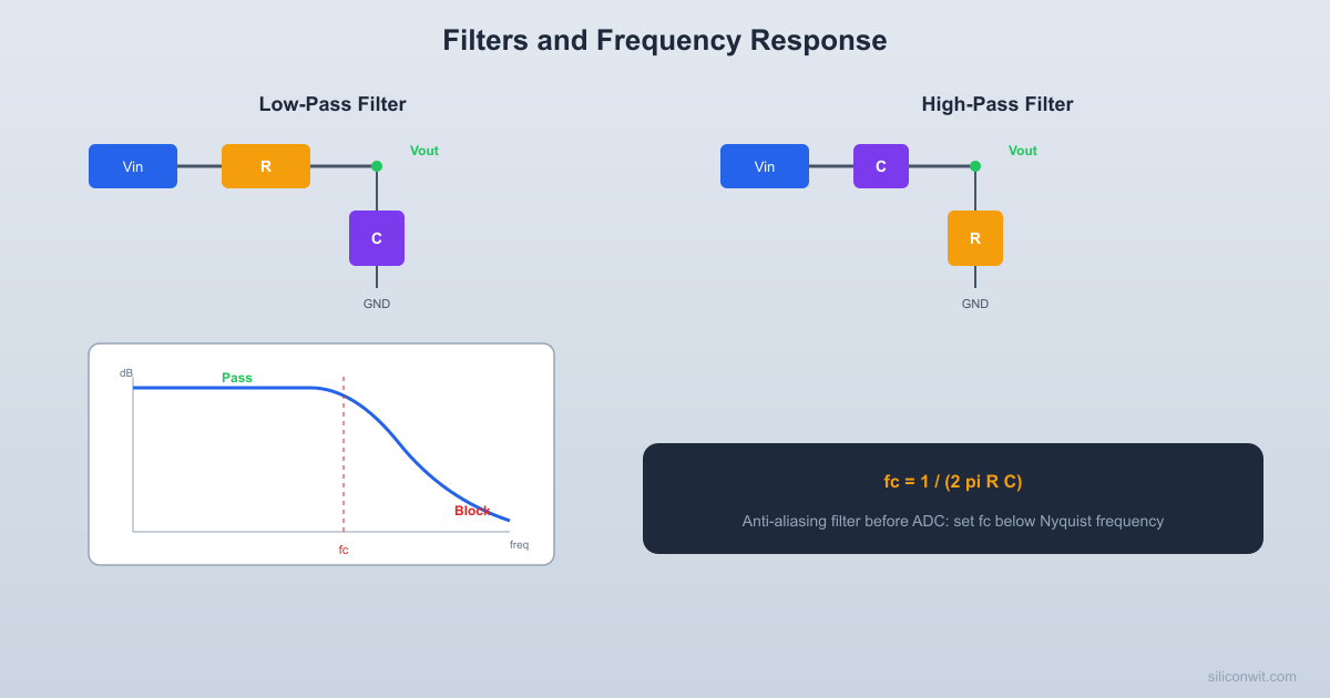
Low-Pass Filter
Passes low frequencies, attenuates high frequencies. Used for smoothing, noise removal, and anti-aliasing before ADC inputs.
High-Pass Filter
Passes high frequencies, attenuates low frequencies. Used for removing DC offset, AC coupling, and blocking slow drift from sensor signals.
Band-Pass Filter
Passes a range of frequencies, attenuates everything above and below. Used for selecting a specific signal frequency from a noisy environment.
Band-Stop (Notch) Filter
Rejects a specific frequency range and passes everything else. Used for removing 50/60 Hz mains hum from sensitive measurements.
The simplest and most commonly used filter in embedded electronics is the RC low-pass filter. You already encountered this in Lesson 2 when studying RC circuits.
A resistor in series, followed by a capacitor to ground:
         [R]  10KVin o---/\/\/---+---o Vout                |              [C] 15nF                |               GND
Low freq: C is open, Vout = Vin High freq: C is short, Vout = 0 fc = 1/(2*pi*10K*15nF) = 1061 HzThe cutoff frequency (also called the -3 dB frequency or corner frequency) is:
At the cutoff frequency, the output signal is attenuated to
The ratio of output to input voltage as a function of frequency:
| Frequency relative to | Output/Input ratio | dB |
|---|---|---|
| 0.995 | -0.04 dB | |
| 0.707 | -3 dB | |
| 0.447 | -7 dB | |
| 0.0995 | -20 dB | |
| 0.01 | -40 dB |
A first-order RC filter has a roll-off of -20 dB per decade (a factor of 10 in frequency). This means that for every 10x increase in frequency above
A Bode plot is a graph that shows a filter’s frequency response. It has two parts:
For a first-order RC low-pass filter:
Magnitude:
Phase:
Decibels (dB) express the ratio of two power or amplitude levels on a logarithmic scale:
| Voltage Ratio | dB |
|---|---|
| 1.0 (no change) | 0 dB |
| 0.707 | -3 dB |
| 0.5 | -6 dB |
| 0.316 | -10 dB |
| 0.1 | -20 dB |
| 0.01 | -40 dB |
| 2.0 | +6 dB |
| 10.0 | +20 dB |
Swap the resistor and capacitor positions to get a high-pass filter:
         [C]  15nFVin o---||------+---o Vout                |              [R] 10K                |               GND
Low freq: C is open, Vout = 0 High freq: C is short, Vout = Vin fc = 1/(2*pi*10K*15nF) = 1061 HzSame formula as the low-pass:
But the behavior is opposite: frequencies below
A band-pass filter combines a high-pass and a low-pass filter in series. It passes frequencies between a lower cutoff (
V_in ── C_HP ──┬── R_HP ──── R_LP ──┬── V_out │ │ GND C_LP │ GNDThe bandwidth is the difference between the two cutoff frequencies:
The center frequency is:
Design the high-pass section first (to set
To pass audio frequencies from 100 Hz to 10 kHz:
High-pass section (
Low-pass section (
When an ADC samples a signal, it can only correctly represent frequencies below half the sampling rate (the Nyquist frequency):
If the input signal contains frequencies above
Example: An ADC sampling at 1 kHz has
Place a low-pass filter before the ADC input with a cutoff frequency at or below the Nyquist frequency. This attenuates frequencies above
For a 1 kHz sampling rate, set
Choose
Close enough to 500 Hz. This single-pole filter provides -20 dB/decade roll-off. At the Nyquist frequency (500 Hz), the signal is attenuated by about 3 dB. At 1 kHz, it is attenuated by about 7 dB. For many applications, this is sufficient. For higher performance, use a two-stage RC filter (-40 dB/decade) or an active filter.
A second-order filter uses two RC stages in series, providing -40 dB/decade roll-off (twice as steep as first-order):
       [R1] 3.3K    [R2] 33KVin o-/\/\/--+---o-/\/\/--+---o Vout             |            |           [C1] 100nF   [C2] 10nF             |            |            GND          GND
  Stage 1          Stage 2  R2 >> R1 to reduce loading  Roll-off: -40 dB/decade
The cutoff frequency of the cascade is not simply the individual cutoff frequency. Due to loading between stages, the effective cutoff is lower:
For accurate second-order filter design, use a Sallen-Key active filter topology (which uses an op-amp and provides precise control over the response shape). But for quick prototyping, two cascaded RC stages with the second R being 10x the first (to reduce loading) works adequately.
When you design active filters, you can choose the response shape:
| Type | Characteristic | Passband | Transition |
|---|---|---|---|
| Butterworth | Maximally flat passband | No ripple | Moderate steepness |
| Chebyshev | Ripple in passband | Some ripple | Steeper transition |
| Bessel | Maximally flat group delay | No ripple | Gentle transition |
For most embedded ADC applications, Butterworth is the standard choice because the flat passband means no signal distortion in the frequency range of interest.
For filters, use 1% metal film resistors when possible. The cutoff frequency depends directly on the resistor value, so a 5% tolerance resistor creates a 5% uncertainty in
The filter’s input source must have a low impedance compared to the filter resistor. If the source impedance is comparable to R, it shifts the cutoff frequency. Solution: buffer the source with an op-amp voltage follower (Lesson 5) before the filter.
| Component | Quantity | Notes |
|---|---|---|
| Breadboard | 1 | From previous lessons |
| Resistors: 1k, 3.3k, 10k, 33k, 100k ohm | 1 each | 1% preferred |
| Capacitors: 100 pF, 1 nF, 10 nF, 100 nF, 1 | 1 each | Ceramic C0G or X7R |
| Function generator (or MCU generating a square wave) | 1 | For frequency sweep |
| Oscilloscope (or MCU with ADC for slow signals) | 1 | For measuring output |
| Digital multimeter | 1 | AC voltage mode |
| Passive buzzer | 1 | For audio demonstration |
| LED + 220 ohm resistor | 1 | For low-frequency visual indicator |
| Jumper wires | Several | Male-to-male |
Choose component values
For a 1 kHz cutoff:
Build the filter Connect the resistor from the input to the output node. Connect the capacitor from the output node to ground.
Connect a signal source If you have a function generator, set it to produce a sine wave at 100 Hz, 1V amplitude. If you are using an MCU, generate a PWM signal and vary the frequency.
Measure the output at several frequencies Sweep the input frequency and measure the output amplitude at each point:
Record the results
Calculate
Plot the response
Plot your measurements on a graph with frequency (log scale) on the horizontal axis and
If you do not have a function generator or oscilloscope, you can still demonstrate filtering:
Use an MCU to generate PWM Program an Arduino or STM32 to generate a square wave at a specific frequency on a GPIO pin.
Build the RC filter Connect the filter between the GPIO pin and an ADC input on the same or different MCU.
Read the ADC at different PWM frequencies
At low frequencies, the ADC will read a signal that toggles between high and low. At high frequencies (well above
Listen to the difference Connect a passive buzzer after the filter. Generate a square wave at 2 kHz (a clear tone). Now put it through the 1 kHz low-pass filter. The buzzer tone becomes muffled because the harmonics that give the square wave its sharp edges are attenuated.
| Frequency (Hz) | Predicted | Measured | Predicted dB | Measured dB |
|---|---|---|---|---|
| 10 | 1.000 | ________ | 0.0 | ________ |
| 100 | 0.995 | ________ | -0.04 | ________ |
| 500 | 0.905 | ________ | -0.87 | ________ |
| 1000 ( | 0.707 | ________ | -3.0 | ________ |
| 2000 | 0.447 | ________ | -7.0 | ________ |
| 5000 | 0.196 | ________ | -14.2 | ________ |
| 10000 | 0.0995 | ________ | -20.0 | ________ |
Watch Out For These
Filters Are Everywhere in MCU Design
| Filter Type | Circuit | Cutoff Formula | Passes |
|---|---|---|---|
| Low-pass (RC) | R series, C to ground | Frequencies below | |
| High-pass (RC) | C series, R to ground | Frequencies above | |
| Band-pass | HP + LP in cascade | Frequencies between cutoffs | |
| First-order roll-off | Single RC stage | N/A | -20 dB/decade |
| Second-order roll-off | Two RC stages | N/A | -40 dB/decade |
| Design Parameter | Key Consideration |
|---|---|
| Anti-aliasing | At or below |
| Component tolerance | Use 1% resistors, C0G capacitors for precision |
| Source impedance | Must be low relative to filter R |
| Load impedance | Must be high relative to filter output impedance |
Next lesson: oscillators and timing circuits. The 555 timer generates precise frequencies using the RC time constants you have been studying, and crystal oscillators provide the stable clock that drives your MCU.
Comments