WS2812B NeoPixel LEDs require a precise 800 kHz signal with specific high and low pulse widths, down to 150 ns tolerance. Most microcontrollers handle this with tightly timed loops or DMA tricks, but the RP2040 has something better: Programmable I/O. In this lesson you will write a PIO assembly program that generates the WS2812B protocol with cycle-exact timing, freeing both CPU cores to do other work while the state machine streams pixel data autonomously. #PIO #WS2812B #StateMachines
What We Are Building
WS2812B PIO LED Driver
A PIO program that drives a strip of 8 WS2812B (NeoPixel) LEDs. The C code fills a pixel buffer and pushes color data to the PIO FIFO. The state machine handles all timing-critical signal generation. You will write the PIO assembly yourself, understanding each instruction and how the state machine executes it.
Project specifications:
Parameter
Value
Protocol
WS2812B (800 kHz NRZ)
PIO Program Size
~8 instructions
LED Count
8 pixels (expandable)
Color Depth
24-bit GRB per pixel
Data Pin
GP2 (configurable)
Timing Accuracy
Cycle-exact via PIO clock divider
CPU Usage During TX
Zero (PIO runs independently)
Bill of Materials
Ref
Component
Quantity
Notes
1
Raspberry Pi Pico
1
From previous lessons
2
WS2812B LED strip
1
8 pixels, 5V version
3
330 ohm resistor
1
Data line series resistor
4
Breadboard + jumper wires
1 set
5
External 5V supply (optional)
1
For strips drawing over 500 mA
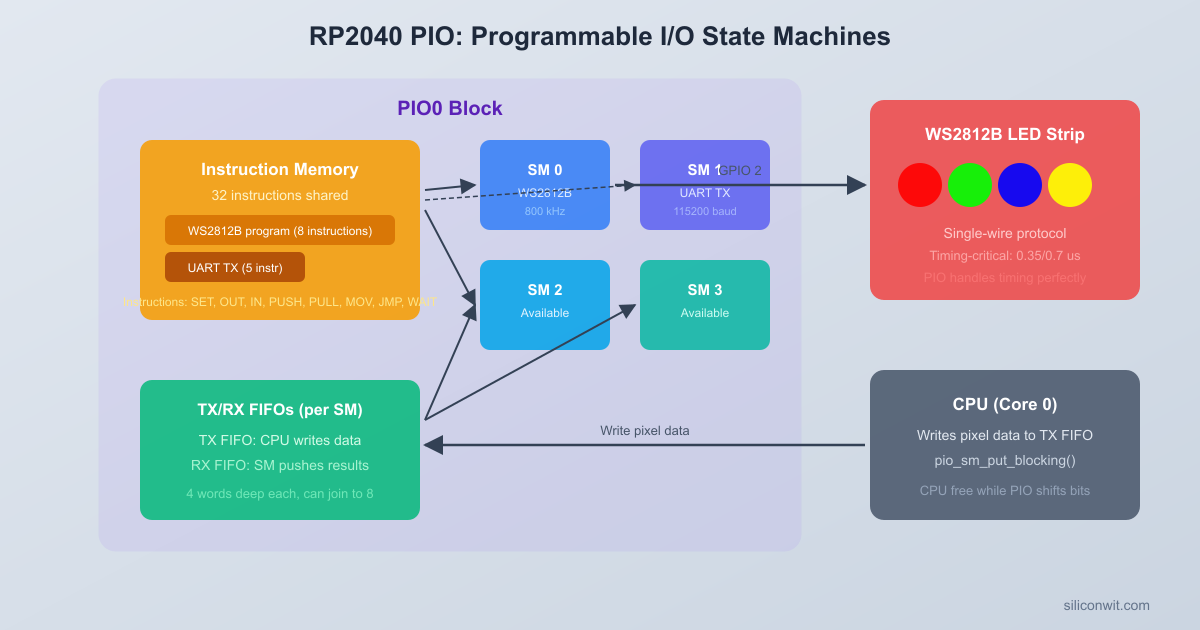
What Is PIO?
The RP2040 has two PIO blocks (PIO0 and PIO1), each containing four state machines. Every state machine is a simple, independent processor that runs a tiny program from a shared 32-instruction memory. These state machines execute one instruction per clock cycle and can toggle GPIO pins with cycle-exact timing.
Why does this matter? Many communication protocols (WS2812B, I2S, SPI variants, UART at unusual baud rates) require precise signal timing. On a typical microcontroller you would bit-bang these protocols in a tight loop, locking the CPU for the entire transfer. PIO offloads that timing-critical work to dedicated hardware: you write a short assembly program, load it into a PIO block, start the state machine, and the CPU is free to do other things.
Each state machine has:
Resource
Description
Two 32-bit shift registers
Input Shift Register (ISR) and Output Shift Register (OSR) for serial data
Two 4-word FIFOs
TX FIFO (CPU to state machine) and RX FIFO (state machine to CPU)
Two scratch registers
X and Y, used for counters, temporaries, and branch conditions
A program counter
Points to the current instruction in the shared instruction memory
A clock divider
Derives the state machine clock from the 125 MHz system clock
Pin mappings
Configurable sets of GPIO pins for input, output, set, and sideset
PIO State Machine Architecture
┌─────────────────────────────────────┐
│ PIO Block (PIO0 or PIO1) │
│ ┌───────────────────────────────┐ │
│ │ Shared Instruction Memory │ │
│ │ (32 x 16-bit instructions) │ │
│ └───────────────────────────────┘ │
│ │
│ State Machine N (1 of 4): │
│ ┌────────┐ ┌─────┐ ┌────────┐ │
│ │ TX FIFO│ │ OSR │ │ GPIO │ │
│ │ 4 words├─>│Shift├─>│ Pins │ │
│ │(CPU in)│ │ Out │ │ (out) │ │
│ └────────┘ └─────┘ └────────┘ │
│ ┌────────┐ ┌─────┐ ┌────────┐ │
│ │ RX FIFO│ │ ISR │ │ GPIO │ │
│ │ 4 words│<─┤Shift│<─┤ Pins │ │
│ │(CPU out│ │ In │ │ (in) │ │
│ └────────┘ └─────┘ └────────┘ │
│ X reg, Y reg, PC, Clock Div │
└─────────────────────────────────────┘
The TX and RX FIFOs decouple the CPU from the state machine. The CPU pushes data into the TX FIFO whenever it is ready; the state machine pulls from it at its own pace. If the FIFO is full, the CPU blocks (or polls). If the FIFO is empty, the state machine stalls until data arrives.
PIO Instruction Set
PIO assembly has exactly nine instructions. Each instruction is encoded in a single 16-bit word, and every instruction executes in exactly one clock cycle (except when it stalls waiting on a condition).
Instruction
Description
jmp
Jump to a label. Can be conditional: jmp !x, jmp pin, jmp !osre, etc.
wait
Stall until a condition is true: a GPIO level, an IRQ flag, or a pin state
in
Shift bits into the ISR from pins, X, Y, null, or the OSR
out
Shift bits out of the OSR to pins, X, Y, null, or the program counter
push
Push the ISR contents into the RX FIFO and clear the ISR
pull
Pull a 32-bit word from the TX FIFO into the OSR
mov
Copy data between registers (X, Y, ISR, OSR, pins, status)
irq
Set, clear, or wait on an IRQ flag (for synchronizing with the CPU or other state machines)
set
Write an immediate value (0 to 31) to pins, X, Y, or pindirs
Sideset
Every PIO instruction can optionally toggle “sideset” pins as a side effect. This happens in parallel with the main instruction, at no extra cost. Sideset is critical for clock-based protocols: the main instruction shifts data while the sideset toggles the clock pin.
For the WS2812B protocol we will use sideset to control the data output pin, letting us set the pin high or low at the exact same cycle that we evaluate a bit value.
Autopush and Autopull
Normally the state machine must execute an explicit push or pull instruction to move data between shift registers and FIFOs. Autopush and autopull automate this: when the shift register has shifted a configurable number of bits (the threshold), the hardware automatically pushes or pulls without consuming an instruction cycle.
For WS2812B, we configure autopull with a threshold of 24 bits. After the state machine shifts out 24 bits (one pixel worth of GRB data), the hardware automatically refills the OSR from the TX FIFO. This means the PIO program never needs an explicit pull instruction in its main loop.
Clock Divider
Each state machine has a 16-bit integer plus 8-bit fractional clock divider. The effective state machine clock is:
f_sm = f_sys / (int + frac/256)
With a 125 MHz system clock and a divider of 1.0, the state machine runs at 125 MHz (8 ns per cycle). For the WS2812B protocol, we need specific cycle counts to match the timing specification, so we will calculate the divider to produce the right total period per bit.
The WS2812B protocol requires an 800 kHz bit rate (1.25 us per bit). If our PIO program uses a specific number of cycles per bit, we set the clock divider so that those cycles add up to 1.25 us.
WS2812B Protocol
The WS2812B datasheet specifies an NRZ (non-return-to-zero) encoding where each bit is a fixed-width pulse:
Symbol
High Time
Low Time
Total Period
Bit 0
T0H: 400 ns (plus or minus 150 ns)
T0L: 850 ns (plus or minus 150 ns)
1.25 us
Bit 1
T1H: 800 ns (plus or minus 150 ns)
T1L: 450 ns (plus or minus 150 ns)
1.25 us
Reset
Low for > 50 us
Both bit 0 and bit 1 start with the line going high. The difference is how long it stays high before going low. For a 0, the high pulse is short (400 ns) and the low pulse is long. For a 1, the high pulse is long (800 ns) and the low pulse is short.
 WS2812B Bit Encoding (NRZ, 800 kHz)          1.25 us Bit 0:  |<-------->|         ┌──┐         │  │ 400ns         │  └────────┐ 850ns         │           │ ────────┘           └────────
 Bit 1:  |<-------->|         ┌───────┐         │       │ 800ns         │       └───┐ 450ns         │           │ ────────┘           └────────
 Reset:  Low for > 50 us (latch data)
The pixel data format is 24 bits per LED in GRB order (green first, then red, then blue), MSB first. For a strip of N LEDs, you send N x 24 bits continuously, then hold the line low for at least 50 us to latch the data.
PIO Program (ws2812.pio)
The classic WS2812 PIO program uses just three instructions in the main loop, plus sideset to control the output pin. Here is the complete .pio file:
ws2812.pio
;
; WS2812B PIO driver
; Drives a WS2812B LED strip using a single GPIO pin.
; Expects GRB pixel data, 24 bits per pixel, MSB first.
;
.program ws2812
.side_set 1
.define public T1 2
.define public T2 5
.define public T3 3
.wrap_target
bitloop:
out x, 1 side 0 [T3 - 1] ; Shift 1 bit from OSR to X. Side-set pin low. Delay T3-1 cycles.
jmp !x do_zero side 1 [T1 - 1] ; If bit is 0, jump to do_zero. Side-set pin high. Delay T1-1 cycles.
jmp bitloop side 1 [T2 - 1] ; Bit is 1: keep pin high for T2 more cycles, then loop.
do_zero:
nop side 0 [T2 - 1] ; Bit is 0: pull pin low for T2 cycles.
.wrap
Let us trace through the timing for each bit value. The state machine runs at 800 kHz x 10 cycles per bit = 8 MHz (or equivalently, we set the divider so each cycle is 125 ns).
Bit = 1 path (high for a long time):
out x, 1 side 0 [T3-1]: Pin goes low, shift out 1 bit. Executes for T3 = 3 cycles (375 ns low from previous bit).
jmp !x do_zero side 1 [T1-1]: X = 1, so the jump is NOT taken. Pin goes high. Executes for T1 = 2 cycles (250 ns high).
jmp bitloop side 1 [T2-1]: Pin stays high. Executes for T2 = 5 cycles (625 ns high). Total high = T1 + T2 = 7 cycles = 875 ns.
Bit = 0 path (high for a short time):
out x, 1 side 0 [T3-1]: Pin goes low, shift out 1 bit. T3 = 3 cycles (375 ns low from previous bit).
jmp !x do_zero side 1 [T1-1]: X = 0, so the jump IS taken. Pin goes high. T1 = 2 cycles (250 ns high). Total high = T1 = 2 cycles = 250 ns.
Both paths take exactly 10 cycles per bit. With a clock divider that gives 125 ns per cycle, the total period is 1.25 us (800 kHz), matching the WS2812B specification.
The .wrap_target and .wrap directives create a free jump: when the program counter reaches .wrap, it instantly returns to .wrap_target without consuming a cycle. This keeps the bit loop running continuously.
How Autopull Feeds the Loop
We configure autopull with a threshold of 24 bits. The out x, 1 instruction shifts one bit at a time from the OSR. After 24 bits have been shifted out, the hardware automatically reloads the OSR from the TX FIFO. If the TX FIFO is empty, the state machine stalls on the out instruction, holding the pin low, which conveniently acts as the reset signal when we are done sending pixel data.
C Host Code
The C code initializes the PIO block, loads the program, configures the state machine, and then writes pixel data to the TX FIFO. The Pico SDK provides helper functions generated from the .pio file.
PIO Initialization
ws2812.c
#include<stdio.h>
#include<stdlib.h>
#include"pico/stdlib.h"
#include"hardware/pio.h"
#include"hardware/clocks.h"
#include"ws2812.pio.h"/* Auto-generated header from ws2812.pio */
The put_pixel() function writes a 32-bit word to the TX FIFO. The pixel data is shifted left by 8 because the OSR shifts MSB first and we use only 24 of the 32 bits. The urgb_u32() helper packs RGB values into GRB order as required by WS2812B.
Color Animations
With the PIO driver running autonomously, the CPU just needs to fill the pixel buffer and push it to the FIFO periodically. Here are three animation functions.
HSV to RGB Conversion
Many color animations are easier to express in HSV (hue, saturation, value) space. This helper converts HSV to the GRB format our driver expects:
pattern_breathe(pio, sm, 160, t); /* Blue breathing */
break;
case2:
pattern_breathe(pio, sm, 0, t); /* Red breathing */
break;
}
sleep_ms(20); /* ~50 FPS refresh rate */
t++;
}
return0;
}
To run the color wipe animation as a one-shot effect, call it from main() before entering the loop:
pattern_color_wipe(pio, sm, urgb_u32(0, 255, 0), 100); /* Green wipe */
sleep_ms(500);
CMakeLists.txt
The build configuration for a PIO project has one extra step compared to a standard Pico SDK project: the pico_generate_pio_header() function. This CMake function runs the PIO assembler on your .pio file and generates a C header containing the assembled program as a constant array, along with helper functions.
The pico_generate_pio_header() call is the key line. At build time, the SDK’s pioasm tool parses ws2812.pio, assembles the instructions into 16-bit words, and writes ws2812.pio.h into the build directory. This header defines ws2812_program (the instruction array), ws2812_program_get_default_config() (returns a pre-filled pio_sm_config), and the timing constants ws2812_T1, ws2812_T2, and ws2812_T3 that we declared with .define public.
Building and Flashing
Create the project directory and place main.c, ws2812.pio, and CMakeLists.txt inside it.
Create the build directory and run CMake:
Terminal window
mkdirbuild && cdbuild
cmake..
Compile the project:
Terminal window
make-j4
The build produces ws2812_pio.uf2 in the build directory.
Connect the Pico in BOOTSEL mode: hold the BOOTSEL button while plugging in the USB cable. The Pico appears as a USB mass storage device.
Copy the firmware to the Pico:
Terminal window
cpws2812_pio.uf2/media/$USER/RPI-RP2/
On macOS the mount point is /Volumes/RPI-RP2/. On Windows, drag the file to the RPI-RP2 drive in File Explorer.
The Pico reboots automatically and the LED strip starts cycling through the animation patterns.
Circuit Wiring
Connect the WS2812B strip to the Pico as follows:
WS2812B Pin
Pico Connection
DIN (data in)
GP2 through 330 ohm resistor
VCC (5V)
VBUS (5V USB) or external 5V supply
GND
GND (shared ground with Pico)
The 330 ohm series resistor on the data line protects the first LED’s input from voltage spikes. For strips longer than 8 LEDs, use an external 5V supply rated for the total current (each WS2812B draws up to 60 mA at full white). Always connect the external supply ground to the Pico ground.
The RP2040 outputs 3.3V logic levels. WS2812B LEDs are specified for 5V logic, but they reliably accept 3.3V signals when powered at 5V. The datasheet minimum input high voltage is 0.7 x VDD = 3.5V, but in practice 3.3V works consistently with nearly all WS2812B strips.
Exercises
Exercise 1: Adjust Timing Constants
Modify the T1, T2, and T3 values in the .pio file. Change T1 to 3, T2 to 3, and T3 to 4 (still 10 cycles total). Observe how the LED colors change or become unstable. Then calculate and set the clock divider to compensate, restoring correct 800 kHz timing. Document the relationship between cycle counts and the required clock divider value.
Exercise 2: Two Independent Strips
Add a second WS2812B strip on GP3. Use a second state machine (sm1) on the same PIO block to drive it independently. Write different animation patterns to each strip simultaneously. Verify that both strips update at the same frame rate without interfering with each other.
Exercise 3: Serial Color Control
Add USB serial input so the user can type a hex color code (for example, FF0000 for red) and the entire strip changes to that color. Parse the 6-character hex string into R, G, B bytes using sscanf() or manual nibble conversion. Print the received color back to confirm.
Exercise 4: Pixel Addressable Commands
Extend Exercise 3 so the user can set individual pixels. Accept commands in the format P3 00FF00 (set pixel 3 to green). Maintain an array of pixel colors in memory and update only the addressed pixel. After each command, push the entire pixel array to the PIO FIFO to refresh the strip.
Summary
PIO is the RP2040’s most distinctive peripheral. Two PIO blocks, each with four state machines and a shared 32-instruction memory, let you implement custom protocols with cycle-exact timing and zero CPU involvement during data transfer. The nine-instruction PIO assembly language is minimal but powerful: combined with sideset, autopush/autopull, and configurable clock dividers, a three-instruction loop can generate the precise 800 kHz NRZ signal that WS2812B LEDs require.
The workflow for any PIO project follows the same pattern: write a .pio assembly file, let pico_generate_pio_header() assemble it into a C header, then use the Pico SDK API to load the program, configure the state machine, and push data through the FIFO. The CPU only touches the FIFO; the state machine handles all pin toggling and timing. In the next lesson, you will use the RP2040’s second Cortex-M0+ core to run code in true parallel, communicating between cores through hardware FIFOs and spinlocks.
Comments