The RP2040 has a built-in USB 1.1 PHY, which means it can be a USB device without any external chip. Plug it into a PC and it can appear as a keyboard, a serial port, a flash drive, or a gamepad. In this lesson you will build a custom USB gamepad using TinyUSB. A thumb joystick controls two analog axes, four buttons map to gamepad buttons, and the whole thing shows up as a standard HID game controller in Windows, macOS, and Linux with zero driver installation. You will write the HID report descriptor by hand, understanding every byte. #USB #HID #TinyUSB
What We Are Building
Custom USB Gamepad
A USB HID gamepad built on the Pico. A thumb joystick module provides X and Y analog axes via ADC. Four push buttons map to gamepad buttons A, B, X, and Y. The firmware uses TinyUSB to present a standard HID gamepad descriptor, so the controller works immediately on any operating system. You will also add a CDC serial interface as a composite device for debug output.
Project specifications:
Parameter
Value
USB Class
HID Gamepad (composite with CDC debug)
Analog Axes
2 (X, Y from thumb joystick via ADC)
Buttons
4 digital inputs
Report Rate
8 ms (125 Hz polling)
Descriptor
Custom HID report descriptor
Compatibility
Windows, macOS, Linux (driverless)
USB Library
TinyUSB (included in Pico SDK)
Bill of Materials
Ref
Component
Quantity
Notes
1
Raspberry Pi Pico
1
From previous lessons
2
Thumb joystick module
1
Dual-axis analog with button
3
Push buttons
4
Momentary tactile switches
4
10K ohm resistors
4
Pull-downs (or use internal pull-ups)
5
Breadboard + jumper wires
1 set
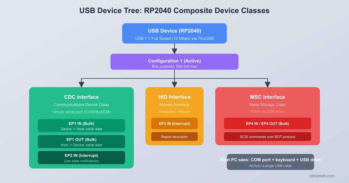
USB Device Architecture
Every USB device describes itself to the host through a hierarchy of descriptors. When you plug in a device, the host reads these descriptors to figure out what the device is, what it can do, and which driver to load. Understanding this hierarchy is essential before writing any TinyUSB code.
Descriptor Hierarchy
USB Descriptor Hierarchy
┌──────────────────────────────────┐
│ Device Descriptor │
│ (VID, PID, USB version) │
│ ┌────────────────────────────┐ │
│ │ Configuration 1 │ │
│ │ ┌──────────────────────┐ │ │
│ │ │ Interface 0: HID │ │ │
│ │ │ (Gamepad) │ │ │
│ │ │ ┌────────────────┐ │ │ │
│ │ │ │ EP1 IN (INT) │ │ │ │
│ │ │ │ 8ms poll, 64B │ │ │ │
│ │ │ └────────────────┘ │ │ │
│ │ └──────────────────────┘ │ │
│ │ ┌──────────────────────┐ │ │
│ │ │ Interface 1: CDC │ │ │
│ │ │ (Debug serial) │ │ │
│ │ │ EP2 IN/OUT (BULK) │ │ │
│ │ └──────────────────────┘ │ │
│ └────────────────────────────┘ │
└──────────────────────────────────┘
The descriptors form a tree with four levels:
Level
Descriptor
Purpose
1
Device Descriptor
Identifies the device: vendor ID, product ID, USB version, device class
2
Configuration Descriptor
Describes a set of interfaces the device can use simultaneously
3
Interface Descriptor
Describes one function (HID, CDC, MSC, etc.) with its class and protocol
4
Endpoint Descriptor
Defines a communication pipe: direction, transfer type, max packet size, polling interval
A single physical device can have multiple configurations, though most devices only use one. Within that configuration, multiple interfaces can coexist. Our gamepad will have two interfaces: one for HID (the gamepad itself) and one for CDC (the debug serial port). This makes it a composite device.
USB Transfer Types
USB defines four transfer types, each suited to different data patterns:
Transfer Type
Guaranteed Bandwidth
Error Recovery
Use Case
Control
No
Yes
Device enumeration, setup requests
Interrupt
Yes (reserved slots)
Yes
HID reports (keyboards, mice, gamepads)
Bulk
No (uses leftover bandwidth)
Yes
Mass storage, CDC serial data
Isochronous
Yes
No
Audio streaming, video
HID devices use interrupt transfers for sending reports at a fixed polling interval. The host polls the device every N milliseconds (the bInterval field in the endpoint descriptor). For our gamepad, we set this to 8 ms, giving 125 reports per second. That is fast enough for responsive gameplay.
How TinyUSB Fits In
TinyUSB is a lightweight USB stack included in the Pico SDK. It handles all the low-level USB protocol: enumeration, descriptor responses, endpoint management, and class-specific protocol details. You provide the descriptors through callback functions, and TinyUSB calls your application code when the host requests or sends data.
The key TinyUSB callbacks you implement are:
tud_descriptor_device_cb(): returns the device descriptor
tud_descriptor_configuration_cb(): returns the configuration descriptor (which includes all interface and endpoint descriptors)
tud_descriptor_string_cb(): returns string descriptors (manufacturer, product, serial number)
tud_descriptor_hid_report_cb(): returns the HID report descriptor
tud_hid_report_complete_cb(): called after a report is sent, used to schedule the next one
tud_hid_set_report_cb() and tud_hid_get_report_cb(): handle host requests for report data
Your main loop calls tud_task() repeatedly to let TinyUSB process USB events. When the device is ready and the host is polling, you call tud_hid_report() to send gamepad data.
HID Class Overview
The Human Interface Device (HID) class covers any device that takes input from or provides output to a human: keyboards, mice, joysticks, gamepads, knobs, sliders, and even some vendor-specific devices. The key feature of HID is that it is self-describing. The HID report descriptor tells the host exactly what data the device sends and how to interpret each bit and byte. This is why HID devices work without custom drivers: the operating system reads the report descriptor and builds a generic input handler automatically.
HID Report Descriptor
The HID report descriptor is a compact binary program written in a domain-specific language defined by the USB HID specification. Each item in the descriptor is a tag followed by data bytes. The tags describe the structure of the reports the device sends and receives.
Report Descriptor Concepts
The descriptor uses a stack-based model with three types of items:
Main items define the data fields: Input, Output, Feature, and Collection
Global items set parameters that apply to all subsequent main items until changed: Usage Page, Logical Minimum, Logical Maximum, Report Size, Report Count
Local items apply only to the next main item: Usage, Usage Minimum, Usage Maximum
Building the Gamepad Descriptor
Our gamepad sends a 3-byte report: one byte for button states (4 buttons in the lower 4 bits, 4 bits of padding) and two bytes for the X and Y axes (signed 8-bit values each). Here is the descriptor byte by byte:
Usage Page (Generic Desktop) and Usage (Game Pad): These two items tell the host this device belongs to the Generic Desktop page (page 0x01), and specifically it is a game pad (usage 0x05). The operating system uses this to route the device to the game controller subsystem.
Collection (Application): Groups everything that follows into one logical device. Every HID report descriptor must start with a collection and end with End Collection.
Buttons section: We switch to Usage Page 0x09 (Button). Usage Minimum 1 and Usage Maximum 4 define four buttons numbered 1 through 4. Each button is 1 bit (Report Size = 1), and there are 4 of them (Report Count = 4). The Input item flags 0x02 mean “Data, Variable, Absolute”: the bits represent actual button states, not relative changes.
Padding: The first byte has 4 button bits, leaving 4 bits unused. We declare 1 field of 4 bits with flags 0x03 (Constant), which tells the host to ignore these bits. Total so far: 1 byte.
Axes section: We switch back to Usage Page 0x01 (Generic Desktop) and declare two usages: X (0x30) and Y (0x31). Each axis is a signed 8-bit value (Report Size = 8, Report Count = 2) with a range of -127 to 127. The Input item flags 0x02 again mean “Data, Variable, Absolute.” Total: 2 more bytes, giving us 3 bytes per report.
The Report Data Structure
The report descriptor defines the binary layout. In C, we represent it as a packed struct:
TinyUSB needs three things from you: a configuration header (tusb_config.h), a descriptors file (usb_descriptors.c), and the correct CMake setup. Let’s build each one.
tusb_config.h
This header tells TinyUSB which features to enable at compile time:
#ifndefTUSB_CONFIG_H
#defineTUSB_CONFIG_H
#include"pico/stdlib.h"
/* Board and MCU selection (Pico SDK handles these) */
#defineCFG_TUSB_MCU OPT_MCU_RP2040
#defineCFG_TUSB_OS OPT_OS_PICO
/* USB device configuration */
#defineCFG_TUD_ENABLED1
/* Enable HID and CDC classes */
#defineCFG_TUD_HID1
#defineCFG_TUD_CDC1
/* Endpoint buffer sizes */
#defineCFG_TUD_HID_EP_BUFSIZE16
#defineCFG_TUD_CDC_EP_BUFSIZE64
#defineCFG_TUD_CDC_RX_BUFSIZE256
#defineCFG_TUD_CDC_TX_BUFSIZE256
#endif /* TUSB_CONFIG_H */
CFG_TUD_HID and CFG_TUD_CDC each set to 1 means one instance of each class. CFG_TUD_HID_EP_BUFSIZE must be at least as large as your largest HID report (3 bytes in our case, so 16 is plenty).
usb_descriptors.c
This file provides all the USB descriptors through TinyUSB callback functions. It is the longest file in the project, but each section is straightforward once you understand the descriptor hierarchy.
#include"tusb.h"
#include"pico/unique_id.h"
#include<string.h>
/* ---------- Device Descriptor ---------- */
staticconsttusb_desc_device_t desc_device = {
.bLength =sizeof(tusb_desc_device_t),
.bDescriptorType = TUSB_DESC_DEVICE,
.bcdUSB =0x0200, /* USB 2.0 */
.bDeviceClass =0x00, /* Defined at interface level */
Device descriptor:bDeviceClass = 0x00 means the class is defined at the interface level, which is required for composite devices (a device with multiple different classes). The vendor ID 0xCafe is a test ID; for a real product you would register with USB-IF. The iManufacturer, iProduct, and iSerialNumber fields are indices into the string descriptor table.
Configuration descriptor: The TUD_CONFIG_DESCRIPTOR macro generates the 9-byte configuration descriptor header. The total length includes the config header plus all interface/endpoint descriptors. The last parameter (100) is the max power in 2 mA units, so 100 means 200 mA.
CDC descriptor:TUD_CDC_DESCRIPTOR generates the CDC ACM (Abstract Control Model) interface pair. CDC requires two interfaces: a communication interface (for control signals like line coding and DTR/RTS) and a data interface (for the actual serial data). The notification endpoint is interrupt IN, and the data endpoints are bulk IN/OUT.
HID descriptor:TUD_HID_DESCRIPTOR generates the HID interface with one interrupt IN endpoint. The polling interval is the last parameter (8 ms = 125 Hz). HID_ITF_PROTOCOL_NONE means this is not a boot-protocol keyboard or mouse; it uses the full report descriptor.
String descriptors: USB strings are UTF-16LE encoded. The callback converts ASCII strings to UTF-16 on the fly. The serial number at index 3 is derived from the Pico’s unique 64-bit flash ID, so each board has a distinct serial number.
Gamepad Firmware
With the descriptors in place, the main firmware reads the joystick and buttons, packs the data into a HID report, and sends it whenever TinyUSB is ready.
Circuit Connections
USB Gamepad Wiring
┌──────────────────┐ ┌──────────────┐
│ Pico │ │ Thumb │
│ GP26 (ADC0) ────┼────┤ Joystick │
│ GP27 (ADC1) ────┼────┤ VRx, VRy │
│ 3V3 ────────────┼────┤ VCC │
│ GND ────────────┼────┤ GND │
│ │ └──────────────┘
│ GP10 ─┤BTN A├── GND
│ GP11 ─┤BTN B├── GND
│ GP12 ─┤BTN X├── GND
│ GP13 ─┤BTN Y├── GND
│ │
│ USB ────────┼──── To PC (HID Gamepad)
└───────┤├─────────┘
Pico Pin
Component
Function
GP26 (ADC0)
Joystick VRx
X axis analog input
GP27 (ADC1)
Joystick VRy
Y axis analog input
GP10
Button A
Digital input with pull-up
GP11
Button B
Digital input with pull-up
GP12
Button X
Digital input with pull-up
GP13
Button Y
Digital input with pull-up
3V3
Joystick VCC
Power
GND
Joystick GND, all button common
Ground
Each button connects between the GPIO pin and GND. We enable the internal pull-up resistors, so the pin reads high when released and low when pressed.
/* Initialize the Pico board (sets up clocks, GPIO) */
board_init();
/* Initialize TinyUSB device stack */
tusb_init();
/* Initialize ADC for joystick */
adc_setup();
/* Initialize button GPIOs */
buttons_setup();
/* Track time for periodic debug output */
uint32_t last_debug_ms =0;
while (1) {
/* Let TinyUSB process USB events */
tud_task();
/* Send HID report if the device is mounted and ready */
if (tud_mounted()) {
send_gamepad_report();
}
/* Print debug info over CDC every 250 ms */
uint32_t now =board_millis();
if (now - last_debug_ms >=250) {
last_debug_ms = now;
cdc_debug_print(&last_report);
}
}
return0;
}
How the Firmware Works
ADC reading:adc_setup() initializes the ADC peripheral and configures GP26 and GP27 as analog inputs. adc_read_channel() selects the input and performs a single 12-bit conversion (0 to 4095). The adc_to_axis() function centers the value, applies a dead zone, and scales to the signed 8-bit range expected by the HID descriptor.
Dead zone: Analog joysticks rarely rest exactly at the electrical midpoint. Without a dead zone, the gamepad would constantly report small random movements even when untouched. The DEAD_ZONE constant of 100 (out of 2048 from center) means roughly the inner 5% of travel is treated as zero.
Button reading: Each button pin is configured as input with an internal pull-up. When the button is pressed, the pin is pulled to GND, so gpio_get() returns 0. The buttons_read() function packs all four states into the lower 4 bits of a byte, matching the HID report descriptor layout.
Report sending:send_gamepad_report() reads all inputs, builds the report struct, and calls tud_hid_report() if the data changed or if a previous transfer just completed. The tud_hid_report_complete_cb() callback sets report_pending = true, which triggers the next report in the following main loop iteration. This creates a continuous stream of reports at the polling rate negotiated during enumeration.
CDC debug: The cdc_debug_print() function formats the current report data as text and writes it to the CDC interface. This lets you open a serial terminal (PuTTY, minicom, or the Arduino serial monitor) and see live button/axis values. The debug output runs at 4 Hz (every 250 ms), much slower than the HID reports, so it does not interfere with gamepad performance.
Adding CDC Debug Output
Making the gamepad a composite device (HID + CDC) requires no extra hardware. The RP2040’s USB controller supports multiple endpoints, and TinyUSB handles the composite descriptor automatically. You already set CFG_TUD_CDC 1 in tusb_config.h and included the CDC descriptor in the configuration descriptor.
When you plug the composite device into a PC, two things appear:
A game controller (HID interface): visible in the OS game controller settings
A serial port (CDC interface): visible as a COM port on Windows, /dev/ttyACM on Linux, or /dev/cu.usbmodem on macOS
The CDC interface is invaluable during development. You can print raw ADC values to verify wiring, check button debounce timing, log descriptor enumeration events, and monitor report send rates. Once the gamepad works correctly, you can disable the debug output or remove CFG_TUD_CDC entirely to simplify the device.
CDC Callbacks
TinyUSB provides optional CDC callbacks for line coding changes and DTR/RTS signals. For simple debug output, you do not need to implement them. The default behavior accepts any baud rate and ignores control signals. If you want to detect when a terminal connects (DTR asserted), you can implement tud_cdc_line_state_cb():
The project is flat with all source files in the root directory. pico_sdk_import.cmake is copied from the Pico SDK (the standard practice for Pico projects). The build directory is created by CMake and contains the final .uf2 file you drag onto the Pico.
CMakeLists.txt and Build
CMakeLists.txt
cmake_minimum_required(VERSION 3.13)
# Pull in the Pico SDK
include(pico_sdk_import.cmake)
project(pico-gamepad C CXX ASM)
set(CMAKE_C_STANDARD 11)
set(CMAKE_CXX_STANDARD 17)
# Initialize the Pico SDK
pico_sdk_init()
add_executable(pico-gamepad
main.c
usb_descriptors.c
)
# Include the current directory for tusb_config.h
target_include_directories(pico-gamepad PRIVATE
${CMAKE_CURRENT_LIST_DIR}
)
# Link against the Pico SDK and TinyUSB libraries
target_link_libraries(pico-gamepad
pico_stdlib
pico_unique_id
hardware_adc
tinyusb_device
tinyusb_board
)
# Disable default USB and UART stdio (we handle USB ourselves via TinyUSB)
pico_enable_stdio_usb(pico-gamepad 0)
pico_enable_stdio_uart(pico-gamepad 0)
# Generate UF2 output for drag-and-drop flashing
pico_add_extra_outputs(pico-gamepad)
Key points in the CMakeLists.txt:
tinyusb_device and tinyusb_board provide the TinyUSB stack. These libraries are included in the Pico SDK, so no external downloads are needed.
pico_unique_id provides pico_get_unique_board_id() for generating the USB serial number.
hardware_adc provides the ADC functions for reading the joystick.
pico_enable_stdio_usb is set to 0 because we manage USB ourselves through TinyUSB. Enabling Pico SDK’s stdio USB would conflict with our custom TinyUSB device.
Build Commands
Copy pico_sdk_import.cmake from the Pico SDK into your project root:
Terminal window
cp$PICO_SDK_PATH/external/pico_sdk_import.cmake.
Create the build directory and run CMake:
Terminal window
mkdirbuild && cdbuild
cmake-DPICO_SDK_PATH=$PICO_SDK_PATH..
Build the project:
Terminal window
make-j$(nproc)
Flash the Pico. Hold the BOOTSEL button while plugging in the USB cable. The Pico mounts as a mass storage device. Copy the UF2 file:
Terminal window
cppico-gamepad.uf2/media/$USER/RPI-RP2/
On macOS the mount point is /Volumes/RPI-RP2/. On Windows, drag the file to the RPI-RP2 drive in File Explorer.
The Pico reboots automatically after the copy completes. It should now appear as both a game controller and a serial port.
Testing
Once the firmware is flashed, verify that the gamepad works on your operating system.
Open Settings > Devices > Devices and Printers (or search for “Set up USB game controllers” in the Start menu).
“Pico Gamepad” should appear in the list of game controllers.
Click Properties to open the test dialog. You should see:
The X and Y axes respond to the joystick. The crosshair moves with your thumb.
Buttons 1 through 4 light up when pressed.
To view the CDC debug output, open Device Manager and find the new COM port under “Ports (COM and LPT).” Open it in PuTTY or the Arduino Serial Monitor at any baud rate (CDC ignores baud rate settings).
Install the joystick testing tools if not already present:
Terminal window
sudoaptinstalljoystick
List connected joystick devices:
Terminal window
ls/dev/input/js*
Run the joystick test utility:
Terminal window
jstest/dev/input/js0
You should see two axes and four buttons updating in real time.
For the CDC serial output, the device appears as /dev/ttyACM0 (or a similar number). Open it with:
Terminal window
screen/dev/ttyACM0115200
Press Ctrl+A then K to exit screen.
For a graphical test, install jstest-gtk:
Terminal window
sudoaptinstalljstest-gtk
jstest-gtk
Open System Information (Apple menu > About This Mac > System Report) and check the USB section. “Pico Gamepad” should appear with the correct vendor and product IDs.
Games and applications that support game controllers (Steam, for example) should detect the gamepad automatically.
For the CDC serial output, the device appears as /dev/cu.usbmodemXXXX. Open it with:
Terminal window
screen/dev/cu.usbmodem*115200
For detailed USB analysis, download Apple’s USB Prober from the developer tools, or use system_profiler SPUSBDataType in Terminal to inspect the descriptor hierarchy.
Troubleshooting
Symptom
Likely Cause
Fix
Device not recognized
Descriptor error
Check total length in configuration descriptor matches actual byte count
Axes stuck at zero
ADC wiring
Verify joystick VCC is connected to 3V3 and GND is connected
Axes jittery at center
Dead zone too small
Increase DEAD_ZONE from 100 to 200
Buttons always pressed
Pull-up not enabled
Check that gpio_pull_up() is called, and buttons wire to GND (not VCC)
CDC port not visible
OS driver issue
On Linux, check that the cdc_acm kernel module is loaded
Experiments
Add a hat switch (D-pad). Wire four more buttons and add a Hat Switch usage to the HID report descriptor. A hat switch reports a direction value (0 to 7 for the eight compass directions, or 0x0F for centered). Modify the report struct to include a uint8_t hat field. This requires changing the report descriptor to include Usage (Hat Switch) with logical min 0, max 7, and a null state for centered.
Add more analog axes. Connect a second joystick module to GP28 (ADC2) and use the joystick button pin as ADC input for a third axis, giving you Rx and Ry (rotation axes). Update the HID report descriptor with Usage 0x33 (Rx) and 0x34 (Ry). This turns the gamepad into a dual-stick controller.
Add force feedback output. Connect a small vibration motor through a transistor to a PWM-capable GPIO. Add an Output report to the HID descriptor with a usage from the Physical Interface Device (PID) usage page. Implement tud_hid_set_report_cb() to read the host’s rumble commands and drive the motor PWM accordingly.
Implement button debouncing. The current firmware reads buttons directly with no debounce filtering. Add a software debounce routine that requires a button to be in the same state for three consecutive reads (at 1 ms intervals) before registering a change. Compare the button behavior before and after, especially with cheap tactile switches that bounce significantly.
Summary
You built a USB HID gamepad from scratch on the RP2040 using TinyUSB. You wrote a HID report descriptor by hand, defining 4 buttons and 2 analog axes. You configured TinyUSB as a composite device with HID and CDC interfaces, giving you both gamepad functionality and a debug serial port. The firmware reads joystick axes via ADC with dead zone compensation, reads buttons with internal pull-ups, and streams HID reports at 125 Hz. The device works on Windows, macOS, and Linux without any custom drivers. You now understand the USB descriptor hierarchy (device, configuration, interface, endpoint), HID report descriptor format (usage pages, logical ranges, report sizes), and the TinyUSB callback architecture for building custom USB devices.
Comments