On simpler chips like the ATmega328P, you toggle a pin and it just works. The STM32 will not even let you read a GPIO until you enable its bus clock, and misconfiguring the clock tree means your UART baud rate is wrong, your timers run at unexpected frequencies, and your SPI link drops bytes. Getting the clocks right first saves hours of debugging later. In this lesson you will map out the full RCC clock tree, learn every GPIO configuration mode the STM32F103 offers, and wire a KY-040 rotary encoder to the Blue Pill to build a scrollable serial menu that exercises input pull-ups, alternate functions, and interrupt-capable pins. #STM32 #GPIO #ClockTree
What We Are Building
Rotary Encoder Menu System
A terminal-based menu where rotating the encoder scrolls through options and pressing the encoder button selects the current item. The menu displays over UART serial at 115200 baud, with the selected item highlighted. The encoder is read using GPIO input with internal pull-ups and simple software debouncing. Clock configuration is done at the register level to understand every RCC register involved.
Project specifications:
Parameter
Value
Board
Blue Pill (STM32F103C8T6)
Encoder
KY-040 rotary encoder module
Encoder pins
CLK on PB6, DT on PB7, SW on PB5
Serial output
USART1 TX on PA9 (115200 baud)
System clock
72 MHz (HSE + PLL)
GPIO modes used
Input pull-up, alternate function push-pull
Debounce method
Software timer (SysTick based)
Bill of Materials
Component
Quantity
Notes
Blue Pill (STM32F103C8T6)
1
From Lesson 1
ST-Link V2 clone
1
From Lesson 1
KY-040 rotary encoder module
1
Includes pull-up resistors on the module
Breadboard
1
From Lesson 1
Jumper wires
5+
For connections
USB-to-serial adapter (optional)
1
If not using ST-Link virtual COM
The RCC Clock Tree
Every peripheral on the STM32 is clocked through the RCC (Reset and Clock Control) module. Before you can use a GPIO port, a timer, or a UART, you must enable its clock in the RCC. If you forget this step, writing to peripheral registers has no effect, and reading them returns zero. This is the single most common mistake when starting with STM32.
Clock Sources
The STM32F103 has four clock sources:
Source
Frequency
Notes
HSI
8 MHz
Internal RC oscillator, less accurate, always available
HSE
4-16 MHz
External crystal (8 MHz on Blue Pill), accurate
LSI
~40 kHz
Internal, used for independent watchdog
LSE
32.768 kHz
External crystal for RTC
PLL Configuration
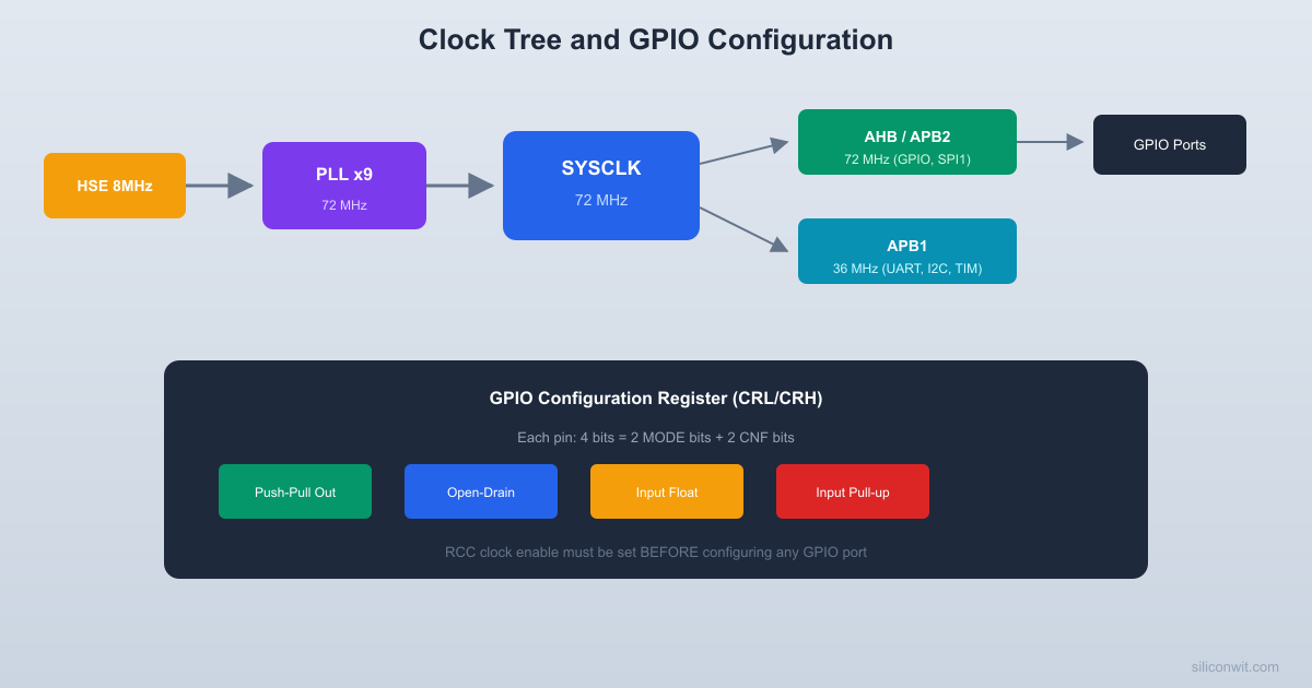
The PLL takes either HSI/2 (4 MHz) or HSE (8 MHz) as input and multiplies it by a factor of 2 to 16. For maximum performance, we use HSE x 9 = 72 MHz. The PLL output feeds the system clock (SYSCLK), which then passes through prescalers for the AHB, APB1, and APB2 buses.
Bus Architecture
HSE (8 MHz) --> PLL (x9) --> SYSCLK (72 MHz)
|
+--> AHB (72 MHz, /1)
| |
| +--> APB2 (72 MHz, /1)
| | GPIO, USART1, SPI1, TIM1, ADC
| |
| +--> APB1 (36 MHz, /2)
| USART2/3, SPI2, TIM2-4, I2C, USB
|
+--> Cortex System Timer (SysTick)
Key points:
AHB (Advanced High-performance Bus): runs at SYSCLK speed, carries DMA, memory, and Cortex core traffic
APB2 (Advanced Peripheral Bus 2): high-speed peripherals including GPIO, USART1, SPI1, ADC, and advanced timer TIM1
APB1: limited to 36 MHz maximum, serves USART2/3, SPI2, I2C, basic timers, and USB
Enabling Peripheral Clocks
/* Enable GPIOA clock (APB2 bus) */
RCC->APB2ENR |= RCC_APB2ENR_IOPAEN;
/* Enable GPIOB clock (APB2 bus) */
RCC->APB2ENR |= RCC_APB2ENR_IOPBEN;
/* Enable USART1 clock (APB2 bus) */
RCC->APB2ENR |= RCC_APB2ENR_USART1EN;
/* Enable TIM2 clock (APB1 bus) */
RCC->APB1ENR |= RCC_APB1ENR_TIM2EN;
GPIO Modes on STM32F103
Each GPIO pin on the STM32F103 is configured by 4 bits in either CRL (pins 0-7) or CRH (pins 8-15). The two MODE bits set direction and speed, while the two CNF bits set the electrical behavior.
  CRL register layout (pins 0-7):
  Bit: 31..28  27..24  23..20  19..16       CNF7 MODE7  CNF6 MODE6  CNF5 MODE5  CNF4 MODE4
  Bit: 15..12  11..8   7..4    3..0       CNF3 MODE3  CNF2 MODE2  CNF1 MODE1  CNF0 MODE0
  Each pin = 4 bits:  +------+------+  | CNF  | MODE |  CNF: 2 bits (config)  | [1:0]| [1:0]|  MODE: 2 bits (direction/speed)  +------+------+
  Example: PA9 as AF push-pull, 50 MHz  CRH bits [7:4] = 0xB = CNF=10, MODE=11
The STM32F103 GPIO system is configured through two 32-bit configuration registers per port: CRL (pins 0-7) and CRH (pins 8-15). Each pin gets 4 bits of configuration, split into 2-bit MODE and 2-bit CNF fields. This is different from newer STM32 families (F4, L4, etc.) that use separate MODER, OTYPER, OSPEEDR, and PUPDR registers. The F103 approach is more compact but less intuitive.
The Four GPIO Modes
Mode
MODE bits
CNF bits
Use case
Input floating
00
01
Default after reset
Input pull-up/pull-down
00
10
Buttons, encoders
Input analog
00
00
ADC channels
Output push-pull
01/10/11
00
Driving LEDs, signals
Output open-drain
01/10/11
01
I2C, level shifting
Alternate function push-pull
01/10/11
10
UART TX, SPI, PWM
Alternate function open-drain
01/10/11
11
I2C SDA/SCL
The MODE bits also set the output speed: 00 = input, 01 = 10 MHz, 10 = 2 MHz, 11 = 50 MHz.
Configuring a Pin (Register Level)
/* PA9 as alternate function push-pull, 50 MHz (USART1 TX) */
/* PA9 is in CRH, position (9-8)*4 = 4 bits starting at bit 4 */
Some peripheral signals can be remapped to alternative pins using the AFIO (Alternate Function I/O) registers. For example, USART1 TX defaults to PA9 but can be remapped to PB6. To use remapped pins, you must enable the AFIO clock and set the appropriate remap bits. In this lesson we use default pin assignments, so no remapping is needed.
/* Enable AFIO clock (required for any remapping) */
RCC->APB2ENR |= RCC_APB2ENR_AFIOEN;
/* Example: remap USART1 to PB6/PB7 (not used in this project) */
AFIO->MAPR |= AFIO_MAPR_USART1_REMAP;
Reading the Rotary Encoder
The KY-040 rotary encoder outputs two quadrature signals (CLK and DT) that are 90 degrees out of phase.
  Quadrature encoder signals:
  Clockwise rotation:  CLK: __    ____    ____    __        |__|    |__|    |__|  DT:     ____    ____    ____       __|    |__|    |__|
  CLK leads DT by 90 degrees.
  Counter-clockwise rotation:  CLK:    ____    ____    ____       __|    |__|    |__|  DT:  __    ____    ____    __        |__|    |__|    |__|
  DT leads CLK by 90 degrees.
  Read DT on CLK falling edge:    DT=1 --> clockwise    DT=0 --> counter-clockwise
When you rotate clockwise, CLK leads DT. When you rotate counterclockwise, DT leads CLK. By reading both signals on each CLK edge, you can determine both the direction and the number of steps. The push button (SW) is a simple active-low signal.
Wiring
KY-040 Pin
Blue Pill Pin
Configuration
CLK
PB6
Input pull-up
DT
PB7
Input pull-up
SW
PB5
Input pull-up
+
3.3V
Power
GND
GND
Ground
Encoder Reading Code
typedefstruct {
int16_t position;
uint8_t last_clk;
uint8_t button_pressed;
uint32_t last_button_time;
} encoder_t;
voidencoder_init(encoder_t*enc) {
/* Enable GPIOB clock */
RCC->APB2ENR|= RCC_APB2ENR_IOPBEN;
/* PB5, PB6, PB7 as input with pull-up */
GPIOB->CRL&=~(0xFFF<<20); /* Clear config for PB5, PB6, PB7 */
GPIOB->CRL|= (0x888<<20); /* Input with pull-up/pull-down */
/* PA9 (TX) as alternate function push-pull, 50 MHz */
GPIOA->CRH&=~(0xF<<4);
GPIOA->CRH|= (0xB<<4);
/* PA10 (RX) as input floating (not used here, but good practice) */
GPIOA->CRH&=~(0xF<<8);
GPIOA->CRH|= (0x4<<8);
/* Baud rate: 115200 at 72 MHz APB2 clock */
/* BRR = 72000000 / 115200 = 625 = 0x271 */
USART1->BRR=0x271;
/* Enable USART, TX */
USART1->CR1= USART_CR1_UE | USART_CR1_TE;
}
voiduart_send_char(charc) {
while (!(USART1->SR& USART_SR_TXE));
USART1->DR= c;
}
voiduart_send_string(constchar*str) {
while (*str) {
uart_send_char(*str++);
}
}
Building the Menu System
SysTick for Timing
volatileuint32_t systick_ms =0;
voidSysTick_Handler(void) {
systick_ms++;
}
voidsystick_init(void) {
/* SysTick reload: 72 MHz / 1000 = 72000 ticks per ms */
SysTick->LOAD=72000-1;
SysTick->VAL=0;
SysTick->CTRL= SysTick_CTRL_CLKSOURCE_Msk |
SysTick_CTRL_TICKINT_Msk |
SysTick_CTRL_ENABLE_Msk;
}
Menu Display
#defineMENU_ITEMS5
constchar*menu_labels[MENU_ITEMS] = {
"1. LED Brightness",
"2. Blink Speed",
"3. Serial Baud Rate",
"4. Clock Info",
"5. Reset Settings"
};
voidmenu_display(int16_tselected) {
/* ANSI escape: clear screen and move cursor home */
uart_send_string("\033[2J\033[H");
uart_send_string("=== STM32 Settings Menu ===\r\n\r\n");
for (int i =0; i < MENU_ITEMS; i++) {
if (i == selected) {
uart_send_string(" > "); /* Highlight selected */
} else {
uart_send_string("");
}
uart_send_string(menu_labels[i]);
uart_send_string("\r\n");
}
uart_send_string("\r\nRotate to navigate, press to select.\r\n");
}
Main Loop
intmain(void) {
clock_init(); /* 72 MHz from HSE + PLL */
systick_init(); /* 1 ms tick */
uart_init(); /* 115200 baud on PA9 */
encoder_t enc;
encoder_init(&enc);
int16_t last_position =0;
int16_t menu_index =0;
menu_display(menu_index);
while (1) {
encoder_update(&enc, systick_ms);
/* Update menu on rotation */
if (enc.position!= last_position) {
int16_t delta =enc.position- last_position;
last_position =enc.position;
menu_index += delta;
/* Wrap around */
if (menu_index <0) menu_index = MENU_ITEMS -1;
if (menu_index >= MENU_ITEMS) menu_index =0;
menu_display(menu_index);
}
/* Handle button press */
if (enc.button_pressed) {
enc.button_pressed=0;
uart_send_string("\r\nSelected: ");
uart_send_string(menu_labels[menu_index]);
uart_send_string("\r\n");
/* Add action handlers here */
for (volatileuint32_t i =0; i <500000; i++);
menu_display(menu_index);
}
}
}
Testing
The UART connection crosses TX to RX between the two devices.
  UART serial connection:
  Blue Pill              USB-Serial Adapter  +----------+           +----------+  |          |           |          |  | PA9  TX -+---------->| RX       |  | PA10 RX -+<----------| TX       |  | GND -----+---------->| GND      |  |          |           |          |  +----------+           +-----+----+                               |                            USB to PC                         (115200 baud)
Connect PA9 (TX) to a USB-to-serial adapter’s RX pin (or use the ST-Link’s virtual COM if supported). Open a serial terminal at 115200 baud. You should see the menu. Rotating the encoder scrolls through options, and pressing it prints the selected item.
What You Have Learned
Lesson 2 Complete
Clock tree knowledge:
Four clock sources (HSI, HSE, LSI, LSE) and their characteristics
PLL configuration for 72 MHz from 8 MHz HSE
AHB and APB bus prescalers and their speed limits
Enabling peripheral clocks through RCC registers
GPIO skills:
All four GPIO modes (input, output, alternate function, analog)
CRL/CRH register configuration with MODE and CNF bit fields
Internal pull-up/pull-down selection via ODR register
Alternate function remapping through AFIO
Peripheral skills:
Reading quadrature encoder signals with direction detection
Software debouncing with SysTick millisecond timer
USART1 initialization and character transmission at register level
Comments