Ceramic Capacitors
Small, cheap, non-polarized. Available from 1 pF to about 10
Resistors respond instantly to voltage changes. Capacitors and inductors do not. They store energy and release it over time, introducing the concept of time-dependent behavior that is fundamental to filtering, timing, power supply smoothing, and signal processing. Every decoupling capacitor on your microcontroller PCB, every debounce circuit on a button input, and every switching power supply relies on these components. #AnalogElectronics #Capacitors #RCCircuits
A capacitor stores energy in an electric field between two conductive plates separated by an insulating material (the dielectric). Think of it as a small rechargeable bucket for electrical charge.
If voltage is water pressure and current is water flow, a capacitor is a flexible membrane stretched across a pipe. When pressure is applied, the membrane stretches and stores energy. When the pressure source is removed, the membrane pushes back, releasing the stored energy. The membrane cannot pass a steady flow (DC is blocked), but it transmits pressure changes (AC passes through).
Capacitance is measured in farads (F). One farad is a very large capacitance. In practice, we work with:
| Unit | Symbol | Value |
|---|---|---|
| Microfarad | ||
| Nanofarad | ||
| Picofarad |
The charge stored on a capacitor is:
Where
The energy stored in a charged capacitor is:
This energy is released when the capacitor discharges. A 1000
That might seem small, but it is enough to damage sensitive ICs if discharged through them suddenly.
Different dielectric materials give capacitors different properties. Here are the types you will encounter most often.
Ceramic Capacitors
Small, cheap, non-polarized. Available from 1 pF to about 10
Electrolytic Capacitors
Polarized (positive and negative leads). Available from 1
Film Capacitors
Non-polarized, stable, low loss. Good for audio circuits and precision timing. More expensive and physically larger than ceramics of the same value.
Rule of thumb for MCU circuits: Place a 100 nF ceramic capacitor as close as possible to every VCC/GND pin pair on your microcontroller. Add a 10
Power 10uF MCU Input +--||--+ +------+ VCC ---+------+----| VCC | | | +-| VCC | | | 100nF | | | | | | GND ---+------+--+-| GND | +------+ Bulk cap Decoupling cap near input at each VCC pinWhen you connect a resistor in series with a capacitor and apply a voltage, the capacitor charges gradually. This is the RC circuit, and its behavior is governed by the time constant.
     SWVCC --/ --+--[R]--+-- Vc           |       |          (charge  [C]           path)   |                  GND
Close SW: C charges through R Open SW: C holds its voltageThe time constant
The time constant has units of seconds. It represents the time it takes for the capacitor to charge to about 63.2% of the applied voltage, or discharge to about 36.8% of its initial voltage.
When a voltage
The current during charging is:
At
| Time | Voltage | Percentage of |
|---|---|---|
| 63.2% | ||
| 86.5% | ||
| 95.0% | ||
| 99.3% |
After
When a charged capacitor discharges through a resistor:
The voltage decays exponentially. After
Calculate the time constant and charging time for
Time to fully charge (to 99.3%):
If you change
If you change
Either decreasing the resistance or decreasing the capacitance makes the circuit respond faster.
An inductor stores energy in a magnetic field created by current flowing through a coil of wire. While capacitors resist changes in voltage, inductors resist changes in current.
Inductance is measured in henrys (H). Common values:
| Unit | Symbol | Value |
|---|---|---|
| Millihenry | ||
| Microhenry |
The voltage across an inductor is:
This means an inductor generates a voltage that opposes any change in current. If you try to suddenly stop current through an inductor, it produces a large voltage spike. This is why flyback diodes are essential when switching inductive loads (motors, relays, solenoids).
For a resistor-inductor (RL) circuit:
The current in an RL circuit rises exponentially when voltage is applied, and decays exponentially when removed, following the same
Capacitors in parallel add directly (the opposite of resistors):
This makes intuitive sense: connecting capacitors in parallel combines their plate areas, increasing total capacitance.
Capacitors in series combine using the reciprocal formula (like resistors in parallel):
Series capacitors are less common in practice, but they appear in voltage multiplier circuits and impedance matching.
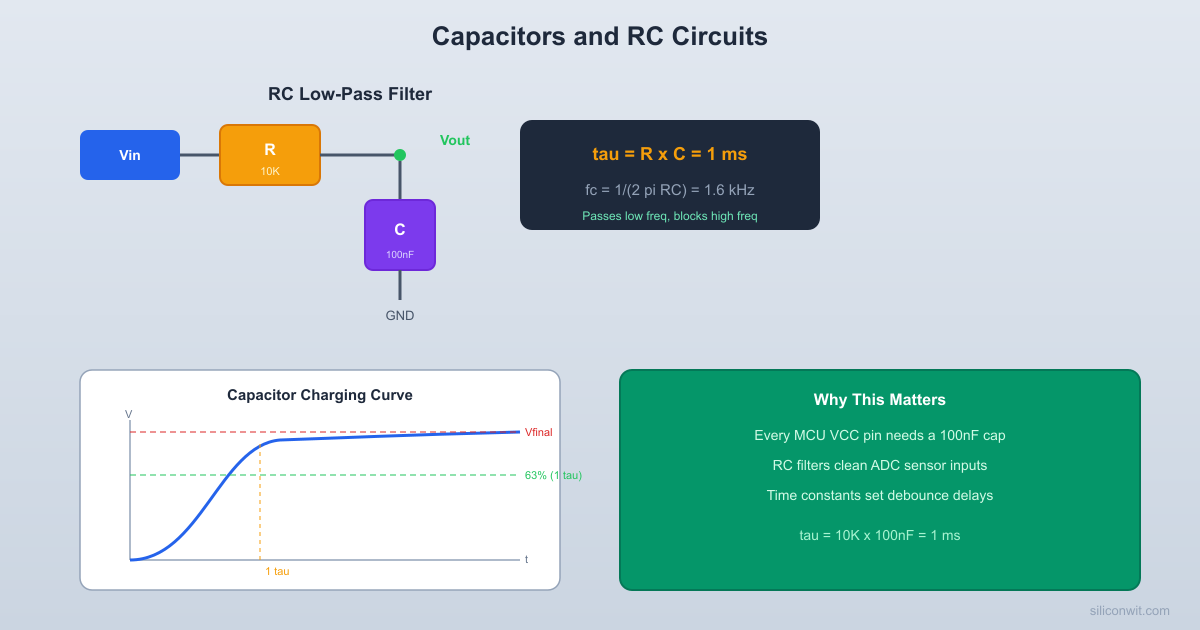
An RC circuit naturally acts as a filter. When a resistor is connected in series and a capacitor to ground, the circuit passes low-frequency signals and attenuates high-frequency signals. This is a low-pass filter.
            [R] 10KVin o---+--/\/\/--+---o Vout                  |                [C] 100nF                  |                 GND
  fc = 1 / (2*pi*R*C)     = 1 / (2*pi*10K*100nF) = 159 Hz  Low freqs pass, high freqs blocked
The cutoff frequency is:
Below this frequency, signals pass through mostly unchanged. Above it, signals are progressively attenuated. We will explore filters in detail in Lesson 7, but the key concept to understand now is that the RC time constant determines the filter’s behavior.
If you feed a square wave into an RC low-pass filter:
This is exactly what happens with decoupling capacitors on a PCB. The capacitor (combined with the trace resistance) forms a low-pass filter that smooths out high-frequency power supply noise while passing the DC supply voltage unchanged.
| Component | Quantity | Notes |
|---|---|---|
| Breadboard | 1 | From Lesson 1 |
| 5V power source | 1 | USB or battery |
| Resistors: 1k, 10k, 100k ohm | 1 each | 1/4 watt |
| Capacitors: 10 | 1 each | 16V or higher rated |
| Capacitor: 100 nF ceramic | 2 | For decoupling demo |
| LED (red) | 1 | For visual charge indicator |
| 220 ohm resistor | 1 | For LED current limit |
| Push button | 1 | Momentary, normally open |
| Digital multimeter | 1 | DC voltage mode |
| Jumper wires | Several | Male-to-male |
This circuit lets you see a capacitor charge and discharge slowly enough to observe with the naked eye.
Build the charging circuit
Connect a 100k ohm resistor from the 5V rail to a breadboard row. Connect a 470
Calculate the time constant
Apply power and observe Connect 5V. The LED will be dim at first and gradually brighten over several minutes as the capacitor charges and the voltage across it rises.
Measure voltage over time
Use your multimeter to measure the voltage across the capacitor at 30-second intervals. Record the values. After one time constant (47 seconds), you should read approximately
Disconnect power and observe discharge Remove the 5V connection. The LED will stay lit and gradually dim as the capacitor discharges through the LED and its resistor. The discharge time constant depends on the parallel resistance of the LED circuit.
Try a faster circuit
Replace the 100k resistor with 10k. Now
Compare capacitor values
Swap the 470
| Time (s) | Predicted Voltage (100k + 470uF) | Measured Voltage |
|---|---|---|
| 0 | 0V | ________ |
| 10 | 0.96V | ________ |
| 20 | 1.72V | ________ |
| 47 ( | 3.16V | ________ |
| 94 ( | 4.33V | ________ |
| 141 ( | 4.75V | ________ |
| 235 ( | 4.97V | ________ |
Your measured values will not match the predictions exactly. Component tolerances (typically 10 to 20% for electrolytic capacitors), multimeter loading, and LED current draw all introduce small differences. If your measurements are within 20% of the predicted values, your circuit is working correctly.
If you have access to a microcontroller board and an oscilloscope (or a logic analyzer with analog input), try this:
Remove the decoupling capacitor from the VCC pin of a microcontroller on a breadboard setup.
Observe the power rail on the oscilloscope. You will see voltage spikes and dips every time the MCU switches its GPIO pins or runs code that draws variable current.
Add a 100 nF ceramic capacitor right at the VCC and GND pins.
Observe again. The noise is dramatically reduced. The capacitor acts as a tiny local energy reserve, supplying current during brief demand spikes and absorbing excess during quiet periods.
This is why every MCU datasheet specifies decoupling capacitors. Without them, the power supply noise can cause erratic behavior, random resets, or corrupted ADC readings.
Watch Out For These
Capacitors Are Everywhere in MCU Circuits
| Concept | Key Equation | Remember |
|---|---|---|
| Capacitance | Charge stored depends on voltage and capacitance | |
| Energy in capacitor | Stored energy can damage components | |
| RC time constant | Time to reach 63.2% of final value | |
| Charging | Exponential rise, 99.3% at | |
| Discharging | Exponential decay | |
| Inductance voltage | Opposes current change | |
| RL time constant | Same exponential behavior as RC | |
| RC cutoff frequency | Transition between pass and stop |
Next up: diodes. These one-way valves for current enable rectification, voltage clamping, and protection circuits that keep your microcontroller safe from voltage spikes and reverse polarity.
Comments