Most microcontrollers force you to interleave tasks on a single core, juggling interrupts and state machines to keep everything responsive. The RP2040 gives you two independent Cortex-M0+ cores with dedicated hardware for safe communication between them. In this lesson, Core 0 runs a waveform generator that outputs audio samples at a fixed rate while Core 1 reads button presses and sends frequency change commands through the inter-core FIFO. Neither core ever waits for the other, and the audio never glitches. #Multicore #DualCore #RP2040
What We Are Building
Dual-Core Tone Synthesizer
A two-core audio synthesizer. Core 0 generates square and sawtooth waveforms at a configurable frequency, outputting to a piezo buzzer via PWM. Core 1 scans four push buttons and sends note commands to Core 0 through the hardware mailbox FIFO. Spinlocks protect a shared configuration struct for more complex parameters. The result is glitch-free audio with responsive input, demonstrating real parallel execution.
Project specifications:
Parameter
Value
Core 0 Task
Waveform generation (PWM audio output)
Core 1 Task
Button scanning and note selection
Inter-Core Comm
Hardware FIFO (32-bit mailbox)
Shared Data
Configuration struct protected by spinlock
Audio Output
PWM on GP18, connected to piezo/speaker
Waveforms
Square wave, sawtooth wave
Note Range
C4 (262 Hz) through C5 (523 Hz)
Bill of Materials
Ref
Component
Quantity
Notes
1
Raspberry Pi Pico
1
From previous lessons
2
Piezo buzzer or small speaker
1
Passive piezo preferred
3
Push buttons
4
Momentary tactile switches
4
10K ohm resistors
4
Pull-down for buttons (or use internal pull-ups)
5
Breadboard + jumper wires
1 set
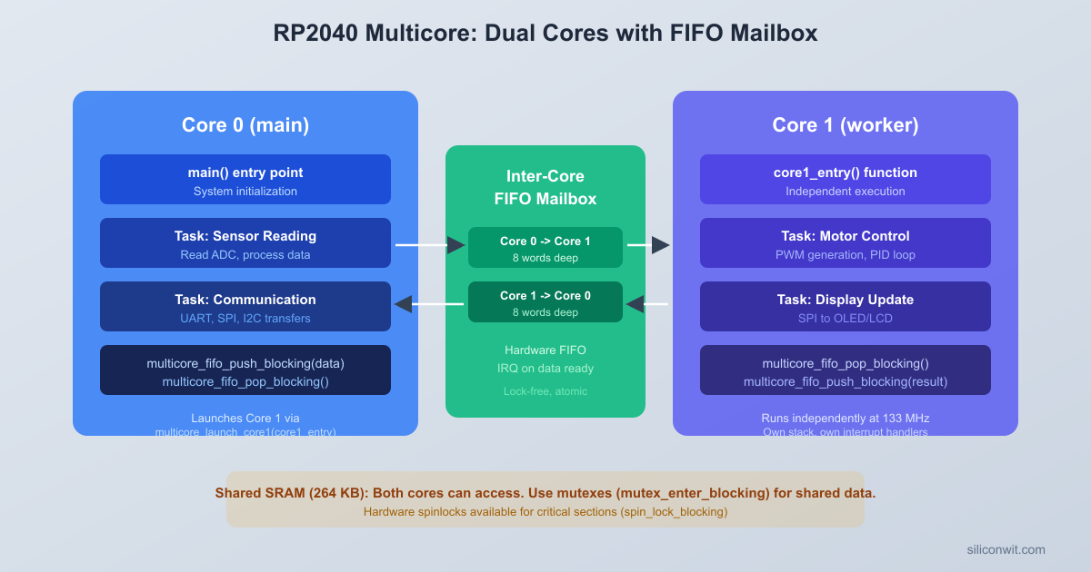
RP2040 Dual-Core Architecture
The RP2040 contains two ARM Cortex-M0+ cores running at 125 MHz. At reset, only Core 0 executes. Core 1 sits in a low-power sleep state, waiting for a launch sequence. Your main() function runs on Core 0, and you explicitly start Core 1 whenever you are ready.
Both cores share the same address space: they see the same flash, SRAM, and peripherals. There is no memory protection between them. This means both cores can read and write any variable, any peripheral register, and any memory address. The shared memory model makes communication simple, but it also means you must be deliberate about synchronization when both cores access the same data.
The RP2040 provides three hardware mechanisms for safe dual-core operation:
The Pico SDK makes launching Core 1 straightforward. You pass a function pointer, and Core 1 begins executing that function:
#include"pico/multicore.h"
voidcore1_entry(void) {
/* This runs on Core 1 */
while (true) {
/* Core 1 work goes here */
}
}
intmain() {
stdio_init_all();
multicore_launch_core1(core1_entry);
/* Continue running on Core 0 */
while (true) {
/* Core 0 work goes here */
}
}
The function you pass to multicore_launch_core1() must never return. If it does, Core 1 will enter a fault state. Always structure it as an infinite loop.
Behind the scenes, the launch mechanism uses the inter-core FIFO to send a startup sequence to Core 1: the vector table address, stack pointer, and entry point. Core 1’s bootrom code listens for this sequence and jumps to your function once it receives valid parameters.
Stack and Memory
Core 1 gets its own stack, allocated from the default Pico SDK linker script. The default Core 1 stack size is 4 KB. If your Core 1 function uses deep recursion or large local arrays, you can increase it by defining PICO_CORE1_STACK_SIZE before including the SDK headers:
#definePICO_CORE1_STACK_SIZE8192
#include"pico/multicore.h"
Both cores share the same 264 KB of SRAM. Global and static variables are accessible from either core. Local variables live on each core’s separate stack.
Inter-Core FIFO
Each RP2040 core has a hardware mailbox FIFO that can hold up to 8 words of 32-bit data. Core 0 pushes to Core 1’s FIFO, and Core 1 pushes to Core 0’s FIFO. These are separate, unidirectional channels.
Inter-Core FIFO Communication
┌──────────────┐ ┌──────────────┐
│ Core 0 │ │ Core 1 │
│ (Waveform │ │ (Button │
│ generator) │ │ scanner) │
│ │ push │ │
│ FIFO_WR ────┼────────>│ FIFO_RD │
│ │ 8 words│ │
│ │ │ │
│ FIFO_RD <───┼─────────┤ FIFO_WR │
│ │ 8 words│ │
│ │ push │ │
└──────────────┘ └──────────────┘
Unidirectional channels, hardware-backed
No cache coherency issues (separate FIFOs)
#include"pico/multicore.h"
/* On Core 0: send a value to Core 1 */
multicore_fifo_push_blocking(42);
/* On Core 1: receive the value from Core 0 */
uint32_t value =multicore_fifo_pop_blocking();
/* value is now 42 */
The blocking variants stall the calling core if the FIFO is full (push) or empty (pop). Non-blocking variants are also available:
/* Returns true if a value was successfully pushed (FIFO not full) */
/* Returns true if a value was available (FIFO not empty) */
uint32_t value;
bool available =multicore_fifo_rvalid(); /* Check without popping */
if (available) {
value =multicore_fifo_pop_blocking();
}
The FIFO is ideal for sending simple commands and small data values. For our synthesizer project, Core 1 will push a 32-bit word that encodes both the note frequency and the waveform type. Core 0 pops these commands and adjusts its audio output.
FIFO Limitations
The FIFO is 8 words deep. If the sender pushes faster than the receiver pops, the FIFO fills up and the sender blocks. For high-throughput data sharing, use shared memory with a spinlock or mutex instead. The FIFO is best for infrequent control messages, not continuous data streams.
Spinlocks
The RP2040 has 32 hardware spinlocks (SIO_SPINLOCK0 through SIO_SPINLOCK31). A spinlock is a single-bit lock backed by hardware: reading the spinlock register atomically tests and sets the lock. If the lock was free, the read returns nonzero and the caller now owns it. If the lock was already held, the read returns zero.
The Pico SDK provides a clean API:
#include"hardware/sync.h"
/* Claim a spinlock (the SDK tracks which are available) */
int spin_lock_num =spin_lock_claim_unused(true);
spin_lock_t*lock =spin_lock_init(spin_lock_num);
/* Acquire the lock (spins until available, disables interrupts) */
uint32_t saved_irq =spin_lock_blocking(lock);
/* Critical section: safe to access shared data */
shared_counter++;
/* Release the lock (restores interrupts) */
spin_unlock(lock, saved_irq);
When a core calls spin_lock_blocking(), two things happen: interrupts are disabled on that core (preventing deadlocks with ISRs), and the core spins in a tight loop reading the spinlock register until the lock becomes available. The returned saved_irq value is passed to spin_unlock() to restore the previous interrupt state.
When to Use Spinlocks
Spinlocks are appropriate when the critical section is very short (a few instructions). The waiting core burns CPU cycles spinning, so you do not want to hold a spinlock while doing lengthy computation or I/O. For our synthesizer, we use a spinlock to protect a small configuration struct that both cores read and write.
The Pico SDK reserves some spinlock numbers for internal use (the striped lock allocator, for example). Always use spin_lock_claim_unused() rather than hardcoding a spinlock number.
Mutex
A mutex is a software construct built on top of spinlocks. The difference is that a mutex can safely be held for longer periods. When a mutex is contended, the waiting core still spins, but the implementation is designed for the common case where the lock is uncontended.
#include"pico/mutex.h"
mutex_t config_mutex;
voidsetup(void) {
mutex_init(&config_mutex);
}
voidupdate_config(void) {
mutex_enter_blocking(&config_mutex);
/* Safe to modify shared configuration */
synth_config.frequency=440;
synth_config.waveform= WAVE_SQUARE;
mutex_exit(&config_mutex);
}
The Pico SDK also provides mutex_try_enter(), which returns immediately with a boolean indicating whether the lock was acquired. This is useful when you want to avoid stalling a real-time loop:
if (mutex_try_enter(&config_mutex, NULL)) {
/* Got the lock, update config */
synth_config.frequency= new_freq;
mutex_exit(&config_mutex);
}
/* If the lock was held, skip the update and try again next iteration */
For our synthesizer project, the mutex protects the shared configuration struct. Core 1 writes new settings when a button is pressed, and Core 0 reads them on every audio sample cycle.
The Synthesizer Project
The dual-core synthesizer divides work cleanly between the two cores:
Core
Responsibility
Timing
Core 0
Audio waveform generation, PWM output
Runs a tight loop at the audio sample rate
Core 1
Button scanning, note selection, FIFO commands
Scans buttons every 10 ms
Core 1 reads four buttons, debounces them, and sends the selected note frequency through the inter-core FIFO. Core 0 receives frequency commands, updates its waveform generator, and outputs audio samples to a PWM pin connected to a piezo buzzer.
Note Definitions
We define four notes corresponding to the four buttons:
#defineNOTE_C4262 /* Hz */
#defineNOTE_E4330
#defineNOTE_G4392
#defineNOTE_C5523
/* Pack note and waveform into a single 32-bit FIFO message */
Core 0 generates audio by computing waveform samples and writing them to the PWM compare register at a fixed rate. The PWM peripheral acts as a simple DAC: a high PWM frequency (well above the audible range) with a varying duty cycle produces an analog-like voltage after filtering by the piezo buzzer’s mechanical inertia.
PWM as Audio Output
We configure the PWM to run at a high frequency (125 kHz) with a wrap value that gives us enough duty cycle resolution:
pwm_config_set_clkdiv(&config, 1.0f); /* Full speed */
pwm_init(slice, &config, true);
pwm_set_gpio_level(AUDIO_PIN, 0);
}
With a 125 MHz system clock and a wrap value of 250, the PWM frequency is 125 MHz / 250 = 500 kHz, far above the audible range. The duty cycle ranges from 0 to 249, giving us 8 bits of effective resolution.
Waveform Sample Computation
Instead of lookup tables, we compute waveform samples directly from a phase accumulator. The phase accumulator increments by a step size proportional to the desired frequency:
The square wave outputs full amplitude for the first half of each cycle and zero for the second half. The sawtooth ramps linearly from 0 to the maximum value. Both waveforms are computed from the 16-bit phase accumulator, so changing the frequency just changes the phase step size.
Circuit Connections
Dual-Core Tone Synthesizer Wiring
┌──────────────────┐
│ Raspberry Pi │
│ Pico │
│ │
│ GP10 ├─┤BTN1├── GND (C4: 262 Hz)
│ GP11 ├─┤BTN2├── GND (E4: 330 Hz)
│ GP12 ├─┤BTN3├── GND (G4: 392 Hz)
│ GP13 ├─┤BTN4├── GND (C5: 523 Hz)
│ (internal pull-ups)
│ │
│ GP18 ├──── Piezo (+)
│ GND ├──── Piezo (-)
│ │
│ USB │
└───────┤├─────────┘
Button Wiring
Four buttons connect to GP10 through GP13 with internal pull-ups enabled. Pressing a button pulls the pin low.
Button
GPIO Pin
Note
Button 1
GP10
C4 (262 Hz)
Button 2
GP11
E4 (330 Hz)
Button 3
GP12
G4 (392 Hz)
Button 4
GP13
C5 (523 Hz)
Speaker Wiring
Component
Pico Connection
Piezo buzzer (+)
GP18
Piezo buzzer (-)
GND
If using a small 8-ohm speaker instead of a piezo, place a 100 ohm resistor in series to limit current. The RP2040 GPIO can source about 12 mA, which is sufficient for a small piezo buzzer but not for driving a speaker directly at high volume.
Waveform Toggle
Long-pressing Button 4 (holding it for over 1 second) toggles between square and sawtooth waveforms. This gives us two waveform modes without adding extra buttons.
The interaction between cores follows a simple pattern:
Core 1 scans buttons every 20 ms. When a button press is detected, it packs the note frequency and waveform type into a 32-bit command and pushes it to the inter-core FIFO.
Core 0 runs a tight audio sample loop. At the top of each iteration, it checks if the FIFO has a pending command. If so, it pops the command, extracts the frequency and waveform, and recalculates the phase step.
Core 0 computes the next waveform sample using the phase accumulator and writes it to the PWM compare register. The PWM hardware converts the digital sample to a pulse-width-modulated signal that drives the piezo buzzer.
For waveform mode changes (triggered by a long press on Button 4), Core 1 also updates a shared configuration struct protected by a mutex. Core 0 reads this struct with mutex_try_enter() to avoid blocking the audio loop.
The FIFO carries time-critical note commands (note on, note off). The mutex-protected struct carries less urgent configuration changes. This two-channel approach keeps the audio loop responsive: it never blocks waiting for a mutex it cannot acquire.
Create the project directory and place main.c and CMakeLists.txt inside it.
Create the build directory and run CMake:
Terminal window
mkdirbuild && cdbuild
cmake..
Compile the project:
Terminal window
make-j4
The build produces multicore_synth.uf2 in the build directory.
Connect the Pico in BOOTSEL mode: hold the BOOTSEL button while plugging in the USB cable. The Pico appears as a USB mass storage device.
Copy the firmware to the Pico:
Terminal window
cpmulticore_synth.uf2/media/$USER/RPI-RP2/
On macOS the mount point is /Volumes/RPI-RP2/. On Windows, drag the file to the RPI-RP2 drive in File Explorer.
The Pico reboots automatically. Press the buttons to play notes. Long-press Button 4 to toggle between square and sawtooth waveforms. Open a serial monitor (115200 baud) to see waveform change messages.
Exercises
Exercise 1: Add Triangle and Sine Waves
Extend the compute_sample() function with two additional waveform types: triangle and sine. For triangle, compute the absolute value of a sawtooth centered at zero. For sine, pre-compute a 256-entry lookup table at startup and index into it using the phase accumulator. Cycle through all four waveforms with the long-press toggle.
Exercise 2: Polyphony with Two Oscillators
Use both cores as separate oscillators. Core 0 generates one tone while Core 1 generates a second tone on a different PWM pin (GP19). Allow two buttons to be pressed simultaneously, with the lower-numbered button assigned to Core 0 and the higher-numbered one to Core 1. You will need to restructure the architecture so that both cores run audio loops and a timer interrupt handles button scanning instead.
Exercise 3: FIFO Throughput Measurement
Write a test program where Core 0 pushes 10,000 values through the FIFO and Core 1 pops them, measuring the total transfer time with time_us_64(). Calculate the throughput in words per second. Then repeat the experiment using shared memory (a ring buffer protected by a spinlock) instead of the FIFO. Compare the throughput of both approaches and explain the difference.
Exercise 4: Core 1 Watchdog
Implement a heartbeat system where Core 1 pushes a “heartbeat” value to the FIFO every 500 ms. Core 0 monitors for this heartbeat and, if it does not arrive within 2 seconds, prints a warning and attempts to reset Core 1 using multicore_reset_core1() followed by multicore_launch_core1(). Test this by intentionally inserting a while(1) hang in Core 1 after a delay.
Summary
The RP2040’s dual-core architecture lets you run two truly parallel tasks with no scheduling overhead and no context switching. Core 0 handles the time-critical audio generation loop while Core 1 manages the human-speed button interface. The hardware inter-core FIFO provides a lightweight, zero-copy channel for passing 32-bit commands between cores, and hardware spinlocks (exposed through the mutex API) protect shared data structures when both cores need read/write access.
The key design principle is to minimize contention. Use the FIFO for infrequent, small messages. Use mutex_try_enter() in real-time loops so the audio core never blocks. Keep shared state small and access it briefly. In the next lesson, you will explore DMA (Direct Memory Access) to move data between peripherals and memory without any CPU involvement, combining it with the multicore and PIO techniques you have learned so far.
Comments