An ESP32 running Wi-Fi draws around 150 mA, which drains two AA batteries in about a day. Deep sleep drops that to under 10 microamps, extending battery life to months or even a year with the right duty cycle. In this lesson you will learn to put the ESP32 into its lowest power states, wake it with timers, GPIO pins, or the ULP coprocessor, and preserve data across sleep cycles in RTC memory. The project is a weather node designed for long-term outdoor deployment on batteries, with power budgeting calculations to predict exactly how long your batteries will last. #ESP32 #DeepSleep #LowPower
What We Are Building
Solar-Ready Weather Node
A battery-powered weather station that wakes every 5 minutes, reads temperature and humidity, connects to Wi-Fi, publishes the data via MQTT, and returns to deep sleep. The ULP coprocessor monitors a rain sensor GPIO while the main cores are off, waking the system immediately on detection. RTC memory stores a message counter and last-known readings across sleep cycles. A full power budget shows expected battery life under different configurations.
Project specifications:
Parameter
Value
MCU
ESP32 DevKitC
Power Source
2x AA batteries (3V nominal)
Deep Sleep Current
Less than 10 uA (with RTC peripherals disabled)
Wake Sources
Timer (5 min default), GPIO (rain sensor), ULP threshold
Active Duration
Approximately 5 to 8 seconds per cycle (sensor read + Wi-Fi + MQTT publish)
Sensor
DHT22 (reused)
Communication
MQTT over Wi-Fi (reuse broker from Lesson 5)
RTC Memory
Message counter, last temperature, last humidity
ULP Program
Monitor GPIO for rain sensor trigger
Estimated Battery Life
4 to 8 months on 2x AA (depending on wake interval)
Bill of Materials
Ref
Component
Quantity
Notes
U1
ESP32 DevKitC
1
Same board from previous lessons
S1
DHT22 temperature/humidity sensor
1
Reused from Lesson 4
B1
2x AA battery holder
1
With leads or JST connector
2x AA batteries
2
Alkaline or lithium recommended
Breadboard + jumper wires
1 set
Circuit Connections
Connect the DHT22 sensor and a push button (simulating a rain sensor trigger) to the ESP32 on a breadboard:
ESP32 Pin
Component
Notes
GPIO 4
DHT22 data pin
10k pull-up resistor to 3.3V
GPIO 25
Push button to GND
ext0 wake source (rain sensor trigger)
3.3V
DHT22 VCC, pull-up resistor
Power supply
GND
DHT22 GND, button GND
Common ground
GPIO 25 is an RTC GPIO, which means it remains functional during deep sleep. Only RTC GPIOs can serve as wake sources. The push button simulates a rain sensor with a digital output: when pressed, it pulls GPIO 25 low, triggering an immediate wake from deep sleep.
For battery-powered operation, connect two AA batteries (3V total) to the ESP32’s 3.3V pin and GND. The ESP32’s onboard voltage regulator accepts input from about 2.3V to 3.6V on the 3.3V pin directly. For voltages above 3.6V, use the VIN pin instead, which feeds through the onboard regulator.
ESP32 Power Modes
The ESP32 offers five distinct power modes, each trading functionality for lower current draw. Understanding them is essential for designing battery-powered applications.
Mode
Typical Current
What Runs
What Is Preserved
Wake Sources
Active
80 to 260 mA
Everything (CPU, Wi-Fi, BT, peripherals)
Everything
N/A (already active)
Modem Sleep
15 to 30 mA
CPU, peripherals; Wi-Fi/BT radio off
RAM, CPU state
Internal (auto, DTIM based)
Light Sleep
0.8 mA
RTC, ULP; CPU paused
RAM, CPU registers, peripherals
Timer, GPIO, touch, UART
Deep Sleep
10 uA
RTC controller, RTC memory, RTC peripherals
RTC slow memory (8 KB)
Timer, ext0/ext1 GPIO, touch, ULP
Hibernation
5 uA
RTC timer only
Nothing (except RTC timer)
Timer only
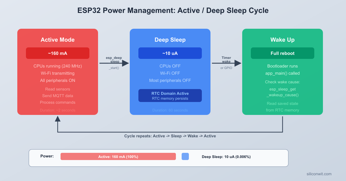
Active mode is the default operating state. Current draw varies widely depending on what peripherals are active. Wi-Fi transmission peaks at around 260 mA, while CPU-only computation with radios off draws about 30 to 50 mA.
Modem Sleep is managed automatically by the Wi-Fi driver when connected to an access point. The radio powers down between DTIM beacon intervals and wakes to receive buffered data. Your code does not need to do anything special; the Wi-Fi stack handles it.
Light Sleep pauses the CPU but preserves full RAM contents and register state. When the chip wakes, execution resumes from the exact instruction where it paused. This is useful when you need sub-second response times and want to keep variables in RAM without the overhead of saving state to RTC memory.
Deep Sleep is the primary mode for battery-powered IoT devices. The main CPUs, most of the RAM, and all digital peripherals are powered off completely. Only the RTC controller, RTC slow memory (8 KB), and optionally the ULP coprocessor remain powered. When the chip wakes from deep sleep, it performs a full reset: the bootloader runs, and app_main() starts from the beginning. Any data you want to preserve across sleep cycles must be stored in RTC memory using special attributes.
Hibernation disables everything except the RTC timer. This achieves the lowest current draw (around 5 uA) but can only wake from a timer. There is no GPIO wake, no ULP, and no RTC memory preservation. Use this mode when you only need periodic time-based wakes with no sensor monitoring during sleep.
Deep Sleep Wake Sources
┌─────────────────┐
Timer ──────────>│ │
(RTC, us prec.) │ │
│ RTC │
ext0 GPIO ─────>│ Controller ├──> Wake + Reset
(single pin) │ │ (app_main()
│ Runs at │ restarts)
ext1 GPIO ─────>│ ~10 uA │
(pin mask) │ │
│ 8 KB RTC │
Touch Pad ─────>│ slow memory │
(any channel) │ preserved │
│ │
ULP Program ───>│ │
(threshold) └─────────────────┘
Deep Sleep Configuration
The core API for deep sleep is straightforward. You configure one or more wake sources, then call esp_deep_sleep_start(). The function never returns. When the chip wakes, it resets completely and runs app_main() from the beginning.
#include"esp_sleep.h"
/* Enable a 5-minute timer wake source */
uint64_t sleep_time_us =5*60*1000000ULL; /* 5 minutes in microseconds */
esp_sleep_enable_timer_wakeup(sleep_time_us);
/* Enter deep sleep (this call never returns) */
esp_deep_sleep_start();
After waking, the ESP32 behaves as if it was just powered on. All variables in regular RAM are reset to their initial values. The Wi-Fi stack is uninitialized. FreeRTOS tasks do not exist yet. Your app_main() function must set everything up from scratch each time.
This is fundamentally different from light sleep, where execution resumes mid-function. In deep sleep, you design your firmware as a one-shot program: initialize, do work, save state, sleep, repeat.
Boot Count Example
A simple way to verify deep sleep is working is to track how many times the device has booted. The RTC_DATA_ATTR attribute places a variable in RTC slow memory, which survives deep sleep resets:
#include<stdio.h>
#include"esp_sleep.h"
#include"esp_log.h"
staticconstchar*TAG ="deep_sleep_demo";
/* This variable survives deep sleep resets */
RTC_DATA_ATTR staticint s_boot_count =0;
voidapp_main(void)
{
s_boot_count++;
ESP_LOGI(TAG, "Boot count: %d", s_boot_count);
/* Do useful work here... */
/* Configure timer wake: 10 seconds */
esp_sleep_enable_timer_wakeup(10*1000000ULL);
ESP_LOGI(TAG, "Entering deep sleep for 10 seconds");
esp_deep_sleep_start();
/* Execution never reaches here */
}
Flash this program and open the serial monitor. You will see the boot count increment with every wake cycle: 1, 2, 3, and so on. Without RTC_DATA_ATTR, the counter would reset to 0 every time because regular RAM is lost during deep sleep.
Wake Sources
The ESP32 supports multiple simultaneous wake sources. You can enable several at once, and the chip wakes when any one of them triggers. After waking, you query esp_sleep_get_wakeup_cause() to determine which source caused the wake.
Timer Wake
Timer wake is the most common source for periodic sensor applications. You specify the sleep duration in microseconds:
/* Wake after 5 minutes */
esp_sleep_enable_timer_wakeup(5*60*1000000ULL);
The RTC timer is reasonably accurate but not crystal-precise. Expect drift of a few percent over long periods. For applications requiring exact timing, synchronize with an NTP server during each active cycle and compensate the sleep duration accordingly.
ext0 Wake (Single GPIO)
The ext0 wake source monitors a single RTC GPIO and wakes the chip when that pin reaches a specified level:
/* Wake when GPIO 25 goes LOW (button pressed, pulled to GND) */
esp_sleep_enable_ext0_wakeup(GPIO_NUM_25, 0);
The second parameter is the trigger level: 0 for low, 1 for high. Only RTC GPIOs work as ext0 wake sources. On the ESP32, these are GPIOs 0, 2, 4, 12, 13, 14, 15, 25, 26, 27, 32, 33, 34, 35, 36, and 39.
You must also configure the internal pull-up or pull-down resistor for the GPIO, since the main GPIO matrix is powered off during deep sleep:
/* Enable internal pull-up on GPIO 25 so it reads HIGH when the button is not pressed */
The call to esp_sleep_pd_config() with ESP_PD_OPTION_ON keeps the RTC peripherals powered during deep sleep, which is required for the internal pull resistors to function.
ext1 Wake (Multiple GPIOs)
The ext1 wake source monitors multiple RTC GPIOs simultaneously. You provide a bitmask of pins and a trigger mode:
/* Wake when ANY of GPIO 25 or GPIO 26 goes LOW */
After waking, call esp_sleep_get_touchpad_wakeup_status() to determine which touch pad triggered the wake.
ULP Wake
The ULP (Ultra Low Power) coprocessor can wake the main processor from deep sleep. This is covered in detail in the ULP coprocessor section below.
Determining the Wake Cause
When your firmware wakes from deep sleep, the first thing it should do (after incrementing the boot count) is check why it woke up. This determines what action to take: a timer wake might mean “read sensors and publish data,” while a GPIO wake might mean “a rain event was detected.”
voidhandle_wakeup_reason(void)
{
esp_sleep_wakeup_cause_t cause =esp_sleep_get_wakeup_cause();
switch (cause) {
case ESP_SLEEP_WAKEUP_TIMER:
ESP_LOGI(TAG, "Woke from timer (periodic reading)");
break;
case ESP_SLEEP_WAKEUP_EXT0:
ESP_LOGI(TAG, "Woke from ext0 GPIO (rain sensor triggered)");
ESP_LOGI(TAG, "Not a deep sleep wake (cold boot or reset)");
break;
}
}
The ESP_SLEEP_WAKEUP_UNDEFINED case handles the first boot after flashing or a power cycle, where the chip was not waking from sleep at all. This distinction is important: on a cold boot, you might want to perform one-time calibration or send a “device online” message.
RTC Memory
RTC slow memory is 8 KB of SRAM powered by the RTC domain. It survives deep sleep resets but is cleared on power-on reset (removing batteries) or when you flash new firmware. Two attributes let you place variables here:
RTC_DATA_ATTR
Variables marked with RTC_DATA_ATTR are stored in RTC slow memory and initialized to zero on power-on reset, just like normal static variables. They retain their values across deep sleep cycles.
Variables marked with RTC_NOINIT_ATTR are also stored in RTC slow memory, but they are never initialized by the bootloader. They survive deep sleep resets, software resets, and even brownout resets. The only thing that clears them is a power-on reset or a flash erase. This is useful for crash counters or watchdog tracking:
RTC_NOINIT_ATTR staticint s_crash_count;
RTC_NOINIT_ATTR staticint s_brownout_count;
voidapp_main(void)
{
esp_reset_reason_t reason =esp_reset_reason();
if (reason == ESP_RST_PANIC) {
s_crash_count++;
ESP_LOGW(TAG, "Crash detected! Total crashes: %d", s_crash_count);
} elseif (reason == ESP_RST_BROWNOUT) {
s_brownout_count++;
ESP_LOGW(TAG, "Brownout detected! Total brownouts: %d", s_brownout_count);
}
}
Since RTC_NOINIT_ATTR variables are never initialized, they contain garbage on the very first power-on. You need a way to detect the first boot. A common pattern is to store a magic number alongside your data:
#defineRTC_MAGIC0xDEADBEEF
RTC_NOINIT_ATTR staticuint32_t s_magic;
RTC_NOINIT_ATTR staticint s_crash_count;
voidapp_main(void)
{
if (s_magic != RTC_MAGIC) {
/* First boot after power-on: initialize */
s_magic = RTC_MAGIC;
s_crash_count =0;
}
/* Now s_crash_count is valid */
}
Practical Uses for RTC Memory
RTC memory is limited to 8 KB, so use it judiciously. Common patterns include:
Boot/message counters for telemetry and diagnostics
Last sensor readings so you can detect rapid changes without a full sensor read cycle
Timestamps of the last successful publish, to adjust sleep duration if a cycle was missed
Wi-Fi channel and BSSID to speed up reconnection (covered in the “Reducing Active Time” section)
Error counters to detect repeated failures and take corrective action (like extending sleep time to conserve battery)
State machine position so multi-step operations can resume after a wake
ULP Coprocessor
The ESP32 contains an Ultra Low Power (ULP) coprocessor: a simple, programmable processor that runs independently while the main Xtensa cores are in deep sleep. It draws only about 150 uA while active and has access to RTC GPIOs, the RTC I2C controller, the ADC, and RTC slow memory. The ULP can perform sensor measurements, monitor GPIO states, and wake the main processor only when specific conditions are met.
This is powerful for threshold-based monitoring. Instead of waking the main cores (and the power-hungry Wi-Fi stack) every few seconds to check a GPIO, you let the ULP check it every 100 milliseconds for almost no power cost. The main cores only wake when something actually happens.
ULP Programming Options
The ESP32 supports two ULP variants:
ULP FSM (Finite State Machine): The original ULP, programmed in a custom assembly language. Available on all ESP32 chips.
ULP RISC-V: A newer RISC-V based coprocessor, programmable in C. Only available on ESP32-S2 and ESP32-S3.
Since we are using the original ESP32, we will use the ULP FSM with its assembly language. The instruction set is small (about 20 instructions) and designed specifically for low-power sensor monitoring.
ULP Assembly Program: GPIO Monitor
The following ULP program monitors GPIO 25 (RTC GPIO 6) and wakes the main processor when it reads LOW. The program runs in a loop, checking the pin at regular intervals:
ulp/monitor_gpio.S
*
* ULP program to monitor RTC GPIO 6 (GPIO 25).
* When the pin reads LOW, the ULP wakes the main processor.
/* If the pin is LOW (0), wake the main processor */
jumpr wake_up, 1, lt
/* Pin is HIGH: go back to sleep, check again after the ULP timer fires */
halt
wake_up:
/* Signal the main processor to wake */
wake
halt
This program uses the READ_RTC_REG macro to read the GPIO state, stores it in a shared variable (gpio_state) that the main processor can also read, and issues a wake instruction if the pin is LOW. The halt instruction puts the ULP back to sleep until its next scheduled wakeup (controlled by the ULP timer period set from the main code).
Loading and Running the ULP from Main Code
The main processor loads the ULP binary, configures the ULP timer period, and starts the ULP before entering deep sleep:
#include"esp_sleep.h"
#include"ulp.h"
#include"ulp/monitor_gpio.h"/* Generated by the build system */
The ulp_set_wakeup_period() call controls how often the ULP runs its program. At 100 ms intervals, the ULP draws a brief pulse of about 150 uA every 100 ms. Averaged over time, this adds roughly 1 to 2 uA to your sleep current, which is negligible compared to the savings from not waking the main cores.
ULP CMakeLists.txt
To build ULP assembly programs, update the main/CMakeLists.txt:
You also need to enable the ULP in sdkconfig or menuconfig. Navigate to Component config, ULP Co-processor and set ULP Co-processor type to ULP FSM. Also enable Enable ULP Co-processor.
Reading ULP Shared Variables from Main Code
After waking from a ULP trigger, the main code can read the shared variables that the ULP program stored in RTC slow memory:
voidapp_main(void)
{
esp_sleep_wakeup_cause_t cause =esp_sleep_get_wakeup_cause();
The & 0xFFFF mask is necessary because ULP variables are 32 bits wide in the memory map but the ULP itself only writes the lower 16 bits. The upper 16 bits contain metadata used by the ULP toolchain.
Power Budget Calculation
Estimating battery life requires calculating the average current draw over a complete duty cycle. The formula is:
The biggest factor is the wake interval. Doubling the interval roughly halves the average current:
Wake Interval
Active Current (avg)
Sleep Current
Average Current
Battery Life (2x AA)
1 minute
100 mA for 5.5 s
0.01 mA for 54.5 s
9.2 mA
11 days
5 minutes
100 mA for 5.5 s
0.01 mA for 294.5 s
1.84 mA
57 days
15 minutes
100 mA for 5.5 s
0.01 mA for 894.5 s
0.61 mA
171 days
30 minutes
100 mA for 5.5 s
0.01 mA for 1794.5 s
0.31 mA
336 days
60 minutes
100 mA for 5.5 s
0.01 mA for 3594.5 s
0.15 mA
1.9 years
At a 15-minute interval, you get almost 6 months on two AA batteries. At 30 minutes, nearly a full year. The lesson is clear: minimize how often you wake up, and minimize how long each active cycle takes.
Reducing Active Time
The Wi-Fi connection phase dominates active time. A cold Wi-Fi connect with DHCP can take 3 to 6 seconds. Several techniques can cut this to under 1 second.
Store Wi-Fi Channel and BSSID
During a normal Wi-Fi scan, the ESP32 scans all channels to find your access point. If you store the channel and BSSID (the access point’s MAC address) in RTC memory, the next connection can skip the scan entirely:
With stored Wi-Fi credentials and a static IP, the connection phase drops from 4 seconds to about 0.5 to 1 second. Recalculating the power budget with a 1-second connection time:
Phase
Duration
Current Draw
Wake, sensor read, fast connect, MQTT publish
2 s
120 mA
Deep sleep (5-minute interval)
298 s
0.01 mA
average_current = (2 * 120 + 298 * 0.01) / 300
= (240 + 2.98) / 300
= 0.81 mA
Battery life: 2500 / 0.81 = 3086 hours = 128 days, or about 4 months. That is more than double compared to the unoptimized version at the same 5-minute interval.
Complete Firmware
The following firmware combines everything covered in this lesson into a single working project: deep sleep with timer and GPIO wake sources, RTC memory for persistent state, ULP coprocessor for GPIO monitoring during sleep, fast Wi-Fi reconnection, MQTT publishing, and power-optimized duty cycling.
/* main.c -- Battery-Powered Weather Node with Deep Sleep
*
* ESP-IDF v5.x project.
* Wakes from deep sleep on timer (5 min) or GPIO (rain sensor on GPIO 25).
* Reads a DHT22 sensor, connects to Wi-Fi (fast reconnect),
* publishes data via MQTT, and returns to deep sleep.
* Tracks boot count and message count in RTC memory.
* ULP coprocessor monitors the rain sensor GPIO during sleep.
The firmware follows a simple one-shot pattern that repeats with every deep sleep wake cycle:
Boot and identify wake cause. The boot count increments in RTC memory, and the wake reason is determined. On a cold boot (first power-on), the wake cause is ESP_SLEEP_WAKEUP_UNDEFINED.
Read the DHT22 sensor. Three attempts are made with 500 ms delays between them. If all attempts fail (which can happen if the sensor is still stabilizing after a cold start), the firmware falls back to the last successful readings stored in RTC memory.
Connect to Wi-Fi with fast reconnect. If the RTC memory contains a valid Wi-Fi channel and BSSID from a previous cycle, the ESP32 skips the channel scan and connects directly. This typically reduces the connection time from 4 seconds to under 1 second. If the fast connect fails twice, the saved info is invalidated and a full scan runs on the next attempt.
Publish via MQTT. The weather data, boot count, message count, and wake reason are published as a JSON payload to the weather topic. An online status message with the retain flag is also published. The MQTT client is created, used, and destroyed within this single cycle.
Enter deep sleep. Two wake sources are configured: a 5-minute timer for periodic readings, and ext0 on GPIO 25 for an immediate wake when the rain sensor triggers. The RTC GPIO pull-up is configured, and the chip enters deep sleep.
Each cycle completes in about 2 to 6 seconds depending on whether a fast or full Wi-Fi connect is needed. During the remaining time (294+ seconds), the chip draws under 10 uA.
CMakeLists.txt and Kconfig Files
Top-Level CMakeLists.txt
cmake_minimum_required(VERSION 3.16)
include($ENV{IDF_PATH}/tools/cmake/project.cmake)
project(weather-node-deepsleep)
main/CMakeLists.txt
idf_component_register(SRCS "main.c"
INCLUDE_DIRS ".")
main/Kconfig.projbuild
menu "Weather Node Configuration"
    config WIFI_SSID        string "Wi-Fi SSID"        default "myssid"        help            SSID of the access point to connect to.
    config WIFI_PASSWORD        string "Wi-Fi Password"        default "mypassword"        help            Password for the access point.
    config MQTT_BROKER_URI        string "MQTT Broker URI"        default "mqtt://broker.hivemq.com:1883"        help            URI of the MQTT broker. Use mqtt:// for unencrypted            or mqtts:// for TLS connections.
    config MQTT_USERNAME        string "MQTT Username"        default ""        help            Username for MQTT broker authentication.            Leave empty if the broker does not require auth.
    config MQTT_PASSWORD        string "MQTT Password"        default ""        help            Password for MQTT broker authentication.
endmenu
Project File Structure
Directoryweather-node-deepsleep/
CMakeLists.txt
Directorymain/
CMakeLists.txt
Kconfig.projbuild
main.c
Building, Flashing, and Testing
Create the project directory and add all files:
Terminal window
mkdir-pweather-node-deepsleep/main
Place the top-level CMakeLists.txt in weather-node-deepsleep/, and place CMakeLists.txt, Kconfig.projbuild, and main.c in weather-node-deepsleep/main/.
Set the target chip:
Terminal window
cdweather-node-deepsleep
idf.pyset-targetesp32
Configure your credentials:
Terminal window
idf.pymenuconfig
Navigate to Weather Node Configuration and enter your Wi-Fi SSID, Wi-Fi password, and MQTT broker URI. If using the free HiveMQ public broker (mqtt://broker.hivemq.com:1883), you can leave the username and password fields empty.
Build the project:
Terminal window
idf.pybuild
Connect the ESP32 DevKitC via USB and flash:
Terminal window
idf.py-p/dev/ttyUSB0flashmonitor
On macOS use /dev/cu.usbserial-XXXX. On Windows use COM3 or the appropriate port.
Watch the serial output for the first boot cycle:
I (456) weather_node: ========================================
I (462) weather_node: Weather Node boot #1
I (466) weather_node: Wake reason: cold_boot
I (470) weather_node: Messages sent so far: 0
I (474) weather_node: ========================================
I (980) weather_node: DHT22: 23.5 C, 58.2% RH
I (982) weather_node: Full Wi-Fi scan (no saved info)
I (4326) weather_node: Wi-Fi connected, channel 6
I (5112) weather_node: Got IP: 192.168.1.105
I (6034) weather_node: MQTT connected
I (6156) weather_node: Published: {"temperature":23.5,"humidity":58.2,...}
I (6358) weather_node: MQTT message published, msg_id=1
I (6360) weather_node: Publish successful (total: 1)
I (6580) weather_node: Entering deep sleep for 300 seconds
I (6582) weather_node: Wake sources: timer (300 s), GPIO 25 (rain sensor)
Wait for the timer wake (5 minutes) and observe the second boot:
I (456) weather_node: ========================================
I (462) weather_node: Weather Node boot #2
I (466) weather_node: Wake reason: timer
I (470) weather_node: Messages sent so far: 1
I (474) weather_node: ========================================
I (980) weather_node: DHT22: 23.4 C, 57.8% RH
I (982) weather_node: Fast reconnect: channel 6
I (1842) weather_node: Wi-Fi connected, channel 6
I (2104) weather_node: Got IP: 192.168.1.105
Notice the fast reconnect on boot #2: the Wi-Fi connection takes about 1 second instead of 4.
Test the GPIO wake by pressing the button on GPIO 25. The serial monitor shows:
I (466) weather_node: Wake reason: rain_sensor
Press Ctrl+] to exit the serial monitor.
Measuring Current Draw
To verify your power budget calculations, you need to measure the actual current consumption. A multimeter with a microamp (uA) range is sufficient for deep sleep measurements.
Measurement Setup
Disconnect the USB cable from the ESP32 (USB draws current through the onboard UART chip even when not communicating).
Set your multimeter to the appropriate current range. For deep sleep measurements, use the uA (microamp) range. For active mode, use the mA (milliamp) range.
Connect the multimeter in series with the battery positive lead. The positive battery terminal connects to the multimeter’s mA/uA input. The multimeter’s COM output connects to the ESP32’s 3.3V pin (or VIN, depending on your battery voltage).
Power on the circuit. The ESP32 will boot, run through its active cycle, and enter deep sleep.
Expected Readings
State
Expected Reading
Notes
Deep sleep (RTC peripherals on)
10 to 15 uA
With ext0 GPIO wake enabled
Deep sleep (RTC peripherals off)
5 to 10 uA
Timer-only wake
Deep sleep with ULP running
15 to 150 uA
Depends on ULP wake frequency
Active (CPU only, no Wi-Fi)
30 to 50 mA
Reading sensors, processing
Active (Wi-Fi connecting)
100 to 160 mA
Scanning channels
Active (Wi-Fi TX)
180 to 260 mA
Transmitting data
Using a Current Profiler
For more detailed analysis, dedicated current profiling tools like the Nordic Power Profiler Kit II or the Joulescope can capture current waveforms over time. These tools show you the exact current profile of each phase (boot, sensor read, Wi-Fi scan, TX burst, sleep entry) and help identify unexpected current spikes or components that fail to power down.
Exercises
Implement adaptive sleep intervals. Modify the firmware so that the sleep duration adjusts based on conditions. If the temperature is changing rapidly (more than 2 degrees between consecutive readings, as stored in RTC memory), reduce the sleep interval to 1 minute to capture the change. If the temperature has been stable for 10 consecutive readings, extend the interval to 15 minutes to conserve battery. Store the stability counter in RTC memory. Add the current sleep interval to the MQTT payload so you can monitor the adaptation from MQTT Explorer.
Add light sleep between sensor read and Wi-Fi connect. After reading the DHT22, enter light sleep for 100 ms before starting Wi-Fi. This is a small optimization, but it demonstrates the difference between light sleep and deep sleep. With light sleep, execution resumes from the exact point where it paused, so you do not lose your sensor readings or local variables. Measure the current draw during this light sleep phase with a multimeter and compare it to the active mode current.
Build a multi-sensor node with ULP threshold monitoring. Add a photoresistor (LDR) to an ADC input and write a ULP program that samples the light level every 500 ms during deep sleep. When the light drops below a threshold (indicating nighttime or heavy clouds), the ULP wakes the main processor to send an alert. The main processor should also read and publish the light level alongside the DHT22 data in each regular timer-triggered cycle. Store the ULP-measured light threshold in RTC memory so the main code can adjust it via MQTT commands.
Implement a battery voltage monitor with low-battery shutdown. The ESP32 can read its own supply voltage using the ADC. Add a voltage divider (two resistors) from the battery positive terminal to an ADC1 input, and read the battery voltage at the start of each wake cycle. Include the battery voltage and estimated remaining percentage in the MQTT payload. When the voltage drops below 2.4V (indicating nearly depleted AA cells), publish a “low-battery” alert and increase the sleep interval to 30 minutes to squeeze out the last bit of battery life. Store the low-battery state in RTC memory so the device stays in conservation mode across reboot cycles.
Summary
You explored the ESP32’s five power modes, from the 260 mA peak of active Wi-Fi transmission down to the 5 uA hibernation state. Deep sleep is the practical choice for most battery-powered applications, providing under 10 uA current draw while preserving 8 KB of RTC slow memory for persistent state across sleep cycles. You learned to configure multiple wake sources simultaneously (timer, ext0 GPIO, ext1 multi-GPIO, touch pad, and ULP), and to determine the wake cause with esp_sleep_get_wakeup_cause() so your firmware can respond appropriately to each trigger type. The RTC_DATA_ATTR and RTC_NOINIT_ATTR attributes let you keep boot counters, sensor readings, Wi-Fi connection info, and state machine positions alive across deep sleep resets. The ULP coprocessor, programmed in its dedicated assembly language, monitors GPIOs during deep sleep at a cost of only 1 to 2 uA averaged, waking the main processor only when a threshold is crossed. Power budget calculations showed that a 5-minute wake interval with fast Wi-Fi reconnection yields about 4 months of battery life on two AA cells, extending to nearly a year at 30-minute intervals. The complete weather node firmware demonstrated the one-shot design pattern for deep sleep applications: boot, identify wake cause, read sensors, connect fast, publish, and sleep again.
Comments