Module (m)
The fundamental size parameter. Module equals the pitch circle diameter divided by the number of teeth:
Downloading gear models from online libraries is fast, but those models rarely match your exact module, tooth count, or pressure angle, and you have no way to verify that the tooth profile is correct. A gear with the wrong involute curve binds under load, wears unevenly, and fails prematurely. Generating gears from parametric equations guarantees mathematical precision and lets you change any parameter (module, tooth count, face width) without starting over. In this lesson you will derive the involute profile from first principles, implement a spur gear generator in CadQuery, verify bending stress with the Lewis equation, and assemble a complete gear train with housing. #InvoluteGears #GearTrain #PythonCAD
By the end of this lesson, you will be able to:
make_spur_gear(module, num_teeth, width)Before writing any code, you need to understand the geometry that makes involute gears work. The involute curve has a remarkable property: when two involute gears mesh, the contact point always lies on a straight line (the line of action), producing a constant velocity ratio regardless of small center-distance errors. This is why involute gears dominate mechanical engineering.
Module (m)
The fundamental size parameter. Module equals the pitch circle diameter divided by the number of teeth:
Pressure Angle (alpha)
The angle between the tooth face and a radial line at the pitch circle. Standard value:
Number of Teeth (z)
Determines the gear ratio when paired with another gear. Minimum practical value is about 17 teeth for 20-degree pressure angle (below this, undercutting occurs unless profile shift is applied).
Face Width (b)
The gear thickness in the axial direction. Typical rule of thumb:
Every gear has four concentric circles that define its geometry:
| Circle | Symbol | Formula | Description |
|---|---|---|---|
| Pitch circle | Where gears “roll” against each other | ||
| Base circle | Where the involute curve originates | ||
| Addendum circle | Outer tip of the teeth | ||
| Dedendum circle | Root of the teeth (includes clearance) |
The addendum (tooth height above pitch circle) is:
The dedendum (tooth depth below pitch circle, including clearance) is:
The total tooth height is therefore
The involute of a circle is the path traced by the end of a taut string unwinding from that circle. Mathematically, for a base circle of radius
where
The involute function (used for angular positioning of teeth) is:
This function appears when calculating the angular thickness of a tooth at any given radius.
At the pitch circle, the angular thickness of one tooth (in radians) is:
This means each tooth occupies half of the angular pitch
The first step is to implement the involute curve as a Python function that returns a list of points suitable for CadQuery:
import cadquery as cqimport mathimport numpy as np
def involute_point(r_base, t):    """    Calculate a single point on the involute of a circle.
    Parameters:        r_base (float): Base circle radius in mm        t (float): Involute parameter (unwinding angle in radians)
    Returns:        tuple: (x, y) coordinates of the involute point    """    x = r_base * (math.cos(t) + t * math.sin(t))    y = r_base * (math.sin(t) - t * math.cos(t))    return (x, y)
def involute_function(alpha):    """    The involute function: inv(alpha) = tan(alpha) - alpha.
    Parameters:        alpha (float): Angle in radians
    Returns:        float: Involute function value    """    return math.tan(alpha) - alpha
def generate_involute_profile(r_base, r_tip, num_points=20):    """    Generate a list of points along an involute curve from the    base circle to the tip circle.
    Parameters:        r_base (float): Base circle radius (mm)        r_tip (float): Addendum (tip) circle radius (mm)        num_points (int): Number of points to generate
    Returns:        list: List of (x, y) tuples along the involute    """    # Calculate the parameter t at the tip circle    # At any point on the involute, the distance from center is:    #   r = r_base * sqrt(1 + t^2)    # So: t_tip = sqrt((r_tip/r_base)^2 - 1)    t_tip = math.sqrt((r_tip / r_base) ** 2 - 1)
    points = []    for i in range(num_points + 1):        t = t_tip * i / num_points        pt = involute_point(r_base, t)        points.append(pt)
return pointsA single gear tooth consists of two involute flanks (left and right), connected by the tip arc at the top and the root fillet at the bottom:
def generate_tooth_profile(module, num_teeth, pressure_angle_deg=20.0,                           num_points=20):    """    Generate the 2D profile of a single gear tooth centered at    the positive X-axis.
    Returns left flank, tip arc, and right flank as point lists.    """    alpha = math.radians(pressure_angle_deg)
    # Circle radii    r_pitch = module * num_teeth / 2.0    r_base = r_pitch * math.cos(alpha)    r_tip = r_pitch + module               # addendum circle    r_root = r_pitch - 1.25 * module       # dedendum circle
    # Handle case where base circle is larger than root circle    r_start = max(r_base, r_root)
    # Generate the right flank involute (positive side)    right_flank = generate_involute_profile(r_base, r_tip, num_points)
    # Tooth angular half-thickness at the pitch circle    # theta_pitch = pi/(2*z) + 2*inv(alpha)/z   (for standard gears)    inv_alpha = involute_function(alpha)
    # Angular half-thickness at the base circle    # The involute starts at angle 0 on the base circle.    # At pitch circle: angle = inv(alpha)    # Tooth half-thickness at pitch circle = pi/(2*z)    # So the tooth center offset = pi/(2*z) + inv(alpha)    tooth_half_angle = math.pi / (2 * num_teeth) + inv_alpha
    # Rotate the right flank so the tooth is centered on the X-axis    right_rotated = []    for (x, y) in right_flank:        angle = tooth_half_angle        xr = x * math.cos(angle) - y * math.sin(angle)        yr = x * math.sin(angle) + y * math.cos(angle)        right_rotated.append((xr, yr))
    # Mirror to get the left flank    left_rotated = [(x, -y) for (x, y) in right_rotated]    left_rotated.reverse()  # reverse order for continuous path
return left_rotated, right_rotated, r_root, r_tipmake_spur_gear()def make_spur_gear(module, num_teeth, width, pressure_angle_deg=20.0, bore_diameter=0, hub_diameter=0, hub_length=0, num_points=20): """ Generate a complete involute spur gear.
Parameters: module (float): Gear module in mm (e.g., 2.0) num_teeth (int): Number of teeth (e.g., 20) width (float): Face width (gear thickness) in mm pressure_angle_deg (float): Pressure angle in degrees (default 20) bore_diameter (float): Central bore diameter in mm (0 = no bore) hub_diameter (float): Hub outer diameter in mm (0 = no hub) hub_length (float): Hub length extending from face in mm num_points (int): Involute curve resolution
Returns: cq.Workplane: Complete spur gear solid """ alpha = math.radians(pressure_angle_deg)
# ─── Calculate circle radii ─── r_pitch = module * num_teeth / 2.0 r_base = r_pitch * math.cos(alpha) r_tip = r_pitch + module r_root = r_pitch - 1.25 * module
# Ensure root radius is positive and reasonable if r_root < 0: raise ValueError( f"Root circle is negative (r_root={r_root:.2f}). " f"Increase module or num_teeth." )
r_start = max(r_base, r_root)
# ─── Involute function value at pressure angle ─── inv_alpha = involute_function(alpha)
# Tooth half-angle at the base circle tooth_half_angle = math.pi / (2 * num_teeth) + inv_alpha
# ─── Generate one tooth profile ─── # Right flank: involute from base circle to tip t_tip = math.sqrt((r_tip / r_base) ** 2 - 1) right_pts = [] for i in range(num_points + 1): t = t_tip * i / num_points pt = involute_point(r_base, t) # Rotate by tooth_half_angle to center tooth on X-axis x = pt[0] * math.cos(tooth_half_angle) \ - pt[1] * math.sin(tooth_half_angle) y = pt[0] * math.sin(tooth_half_angle) \ + pt[1] * math.cos(tooth_half_angle) right_pts.append((x, y))
# Left flank: mirror of right flank left_pts = [(x, -y) for (x, y) in right_pts] left_pts.reverse()
# ─── Build the complete gear outline ─── # Strategy: for each tooth, draw left_flank -> tip_arc -> right_flank # then root_arc to the next tooth angular_pitch = 2 * math.pi / num_teeth
all_points = [] for i in range(num_teeth): angle = i * angular_pitch
cos_a = math.cos(angle) sin_a = math.sin(angle)
# Rotate left flank points for (x, y) in left_pts: xr = x * cos_a - y * sin_a yr = x * sin_a + y * cos_a all_points.append((xr, yr))
# Tip arc point (at the tip of the tooth) # Use the last point of left flank and first of right flank # to interpolate across the tip tip_mid_x = r_tip * math.cos(angle) tip_mid_y = r_tip * math.sin(angle) all_points.append((tip_mid_x, tip_mid_y))
# Rotate right flank points for (x, y) in right_pts: xr = x * cos_a - y * sin_a yr = x * sin_a + y * cos_a all_points.append((xr, yr))
# Root arc: connect to next tooth's left flank # Midpoint of root arc between this tooth and the next next_angle = angle + angular_pitch / 2.0 root_x = r_root * math.cos(next_angle + angular_pitch * 0.05) root_y = r_root * math.sin(next_angle + angular_pitch * 0.05) all_points.append((root_x, root_y))
# ─── Create the 2D profile as a CadQuery wire ─── # Close the loop by repeating the first point, then use polyline all_points.append(all_points[0]) wp = cq.Workplane("XY") gear_profile = wp.polyline(all_points).close()
# Extrude to create the 3D gear body gear = gear_profile.extrude(width)
# ─── Add bore if specified ─── if bore_diameter > 0: gear = ( gear .faces(">Z") .workplane() .hole(bore_diameter) )
# ─── Add hub if specified ─── if hub_diameter > 0 and hub_length > 0: hub = ( cq.Workplane("XY") .workplane(offset=width) .circle(hub_diameter / 2.0) .extrude(hub_length) ) gear = gear.union(hub)
# Bore through the hub as well if bore_diameter > 0: hub_bore = ( cq.Workplane("XY") .workplane(offset=width) .circle(bore_diameter / 2.0) .extrude(hub_length) ) gear = gear.cut(hub_bore)
# ─── Add keyway (optional, for shaft coupling) ─── # Standard DIN 6885 keyway dimensions could be added here
return gearfrom ocp_vscode import show
# ─── Basic gear: module 2, 20 teeth, 10mm wide ───gear_basic = make_spur_gear( module=2.0, num_teeth=20, width=10.0,)show(gear_basic)
# ─── Gear with bore and hub ───gear_with_hub = make_spur_gear( module=2.5, num_teeth=30, width=15.0, bore_diameter=12.0, hub_diameter=25.0, hub_length=10.0,)show(gear_with_hub)
# ─── Small pinion (17 teeth — minimum for no undercutting) ───pinion = make_spur_gear( module=1.5, num_teeth=17, width=8.0, bore_diameter=6.0,)show(pinion)
# ─── Large gear (60 teeth) ───large_gear = make_spur_gear( module=1.5, num_teeth=60, width=8.0, bore_diameter=15.0,)show(large_gear)def gear_dimensions(module, num_teeth, pressure_angle_deg=20.0): """ Print all key dimensions for a spur gear.
Parameters: module (float): Gear module in mm num_teeth (int): Number of teeth pressure_angle_deg (float): Pressure angle in degrees """ alpha = math.radians(pressure_angle_deg)
d_pitch = module * num_teeth d_base = d_pitch * math.cos(alpha) d_tip = d_pitch + 2 * module d_root = d_pitch - 2.5 * module addendum = module dedendum = 1.25 * module tooth_height = addendum + dedendum circular_pitch = math.pi * module tooth_thickness = circular_pitch / 2.0
print(f"{'='*50}") print(f"Gear Dimensions: m={module}, z={num_teeth}, " f"alpha={pressure_angle_deg} deg") print(f"{'='*50}") print(f"Pitch circle diameter: {d_pitch:.3f} mm") print(f"Base circle diameter: {d_base:.3f} mm") print(f"Tip (addendum) diameter: {d_tip:.3f} mm") print(f"Root (dedendum) diameter: {d_root:.3f} mm") print(f"Addendum: {addendum:.3f} mm") print(f"Dedendum: {dedendum:.3f} mm") print(f"Total tooth height: {tooth_height:.3f} mm") print(f"Circular pitch: {circular_pitch:.3f} mm") print(f"Tooth thickness (pitch): {tooth_thickness:.3f} mm") print(f"{'='*50}")
# Examplegear_dimensions(2.0, 20)gear_dimensions(2.5, 40)Two involute gears mesh correctly when they share the same module and pressure angle. The center distance is determined by their pitch circle radii.
For a pair of gears with teeth counts
This is the standard center distance, the exact distance between shaft centers for zero backlash. In practice, you add a small amount of backlash to prevent binding:
where
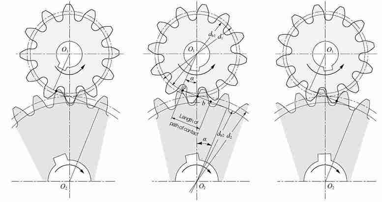
The contact ratio
where
Backlash is the gap between meshing teeth when one gear is held stationary. Some backlash is necessary to prevent jamming from thermal expansion, manufacturing tolerances, and lubrication space. For 3D-printed gears, typical backlash values are:
| Printing Method | Recommended Backlash |
|---|---|
| FDM (0.4mm nozzle) | 0.15 - 0.25 mm |
| SLA (standard resin) | 0.08 - 0.15 mm |
| SLS (nylon) | 0.10 - 0.20 mm |
| CNC machined | 0.02 - 0.05 mm |
Backlash can be introduced by either increasing the center distance or reducing the tooth thickness.
def make_gear_pair(module, z1, z2, width, pressure_angle_deg=20.0,                   backlash=0.1, bore1=0, bore2=0):    """    Generate a meshing pair of involute spur gears.
    Parameters:        module (float): Common module in mm        z1 (int): Number of teeth on pinion (smaller gear)        z2 (int): Number of teeth on gear (larger gear)        width (float): Face width in mm (same for both)        pressure_angle_deg (float): Common pressure angle        backlash (float): Backlash allowance in mm        bore1 (float): Pinion bore diameter (0 = no bore)        bore2 (float): Gear bore diameter (0 = no bore)
    Returns:        tuple: (pinion, gear, center_distance) — both positioned for meshing    """    alpha = math.radians(pressure_angle_deg)
    # ─── Standard center distance ───    r1 = module * z1 / 2.0   # pinion pitch radius    r2 = module * z2 / 2.0   # gear pitch radius    center_distance = r1 + r2 + backlash
    # ─── Contact ratio check ───    r_a1 = r1 + module           # pinion addendum radius    r_b1 = r1 * math.cos(alpha)  # pinion base radius    r_a2 = r2 + module           # gear addendum radius    r_b2 = r2 * math.cos(alpha)  # gear base radius
    eps_num = (        math.sqrt(r_a1**2 - r_b1**2) +        math.sqrt(r_a2**2 - r_b2**2) -        center_distance * math.sin(alpha)    )    eps_den = math.pi * module * math.cos(alpha)    contact_ratio = eps_num / eps_den
    print(f"Gear pair: z1={z1}, z2={z2}, m={module}")    print(f"  Center distance: {center_distance:.3f} mm")    print(f"  Gear ratio: {z2/z1:.3f}:1")    print(f"  Contact ratio: {contact_ratio:.3f}")    if contact_ratio < 1.2:        print(f"  WARNING: Contact ratio < 1.2 — consider more teeth")
    # ─── Generate both gears ───    pinion = make_spur_gear(        module, z1, width,        pressure_angle_deg=pressure_angle_deg,        bore_diameter=bore1,    )    gear = make_spur_gear(        module, z2, width,        pressure_angle_deg=pressure_angle_deg,        bore_diameter=bore2,    )
    # ─── Position the gears for meshing ───    # Pinion at origin, gear offset by center distance along X    # Rotate the gear so teeth interleave properly    # The angular offset for meshing:    #   half-tooth rotation on the gear to fit between pinion teeth    mesh_angle = math.pi / z2  # rotate gear by half a tooth pitch
    gear = (        gear        .rotate((0, 0, 0), (0, 0, 1), math.degrees(mesh_angle))        .translate((center_distance, 0, 0))    )
    return pinion, gear, center_distance
from ocp_vscode import show
# ─── 2:1 reduction pair ───pinion, gear, cd = make_gear_pair( module=2.0, z1=20, z2=40, width=10.0, backlash=0.15, # suitable for FDM printing bore1=8.0, bore2=12.0,)show(pinion, gear)print(f"Center distance: {cd:.2f} mm")print(f"Gear ratio: {40/20:.1f}:1")
# ─── 3:1 reduction pair ───pinion_3, gear_3, cd_3 = make_gear_pair( module=1.5, z1=18, z2=54, width=8.0, backlash=0.12, bore1=6.0, bore2=10.0,)show(pinion_3, gear_3)def contact_ratio_analysis(module, z1, z2, pressure_angle_deg=20.0): """ Detailed contact ratio analysis for a gear pair. """ alpha = math.radians(pressure_angle_deg)
r1 = module * z1 / 2.0 r2 = module * z2 / 2.0 a = r1 + r2 # standard center distance
r_a1 = r1 + module r_b1 = r1 * math.cos(alpha) r_a2 = r2 + module r_b2 = r2 * math.cos(alpha)
# Length of path of contact path_approach = math.sqrt(r_a2**2 - r_b2**2) - r2 * math.sin(alpha) path_recess = math.sqrt(r_a1**2 - r_b1**2) - r1 * math.sin(alpha) total_path = path_approach + path_recess
# Base pitch p_b = math.pi * module * math.cos(alpha)
# Contact ratio eps = total_path / p_b
print(f"{'='*50}") print(f"Contact Ratio Analysis: z1={z1}, z2={z2}, m={module}") print(f"{'='*50}") print(f"Path of approach: {path_approach:.3f} mm") print(f"Path of recess: {path_recess:.3f} mm") print(f"Total path: {total_path:.3f} mm") print(f"Base pitch: {p_b:.3f} mm") print(f"Contact ratio: {eps:.3f}") print(f"Status: {'OK' if eps >= 1.2 else 'LOW — increase teeth'}") print(f"{'='*50}")
return eps
# Analyze several common gear ratioscontact_ratio_analysis(2.0, 20, 40)contact_ratio_analysis(2.0, 17, 51) # 3:1 ratiocontact_ratio_analysis(2.0, 14, 42) # 3:1 with fewer teethThe Lewis equation is the classical method for estimating bending stress at the root of a gear tooth. It treats each tooth as a cantilever beam loaded at its tip.
where:
The tangential force relates to transmitted torque:
where
The Lewis form factor
| Number of Teeth | Lewis Form Factor |
|---|---|
| 12 | 0.245 |
| 14 | 0.276 |
| 17 | 0.303 |
| 20 | 0.320 |
| 25 | 0.340 |
| 30 | 0.358 |
| 40 | 0.389 |
| 50 | 0.408 |
| 60 | 0.421 |
| 75 | 0.435 |
| 100 | 0.447 |
| 150 | 0.460 |
| 300 | 0.472 |
| Rack (inf) | 0.484 |
def lewis_bending_stress(module, num_teeth, width, torque_Nm,                         pressure_angle_deg=20.0):    """    Calculate the Lewis bending stress at the tooth root.
    Parameters:        module (float): Gear module in mm        num_teeth (int): Number of teeth        width (float): Face width in mm        torque_Nm (float): Applied torque in N-m        pressure_angle_deg (float): Pressure angle in degrees
    Returns:        dict: Stress analysis results    """    # Lewis form factor lookup (20-degree pressure angle)    lewis_table = {        12: 0.245, 14: 0.276, 17: 0.303, 20: 0.320,        25: 0.340, 30: 0.358, 35: 0.374, 40: 0.389,        45: 0.399, 50: 0.408, 60: 0.421, 75: 0.435,        100: 0.447, 150: 0.460, 200: 0.468, 300: 0.472,    }
    # Interpolate Lewis form factor    keys = sorted(lewis_table.keys())    if num_teeth <= keys[0]:        Y = lewis_table[keys[0]]    elif num_teeth >= keys[-1]:        Y = lewis_table[keys[-1]]    else:        # Linear interpolation        for i in range(len(keys) - 1):            if keys[i] <= num_teeth <= keys[i+1]:                t = (num_teeth - keys[i]) / (keys[i+1] - keys[i])                Y = lewis_table[keys[i]] * (1 - t) \                  + lewis_table[keys[i+1]] * t                break
    # Pitch circle diameter    d = module * num_teeth  # mm
    # Tangential force    torque_Nmm = torque_Nm * 1000.0  # convert to N-mm    F_t = 2 * torque_Nmm / d         # tangential force in N
    # Lewis bending stress    sigma_b = F_t / (width * module * Y)  # MPa
    # Common material allowable stresses    materials = {        "PLA (3D printed)":        25,   # MPa        "ABS (3D printed)":        30,        "Nylon PA12 (SLS)":        45,        "Acetal (POM)":            60,        "Steel (case hardened)":   250,        "Steel (through hardened)": 350,    }
    results = {        "module": module,        "num_teeth": num_teeth,        "width": width,        "torque_Nm": torque_Nm,        "pitch_diameter": d,        "lewis_factor_Y": Y,        "tangential_force_N": F_t,        "bending_stress_MPa": sigma_b,    }
    print(f"{'='*55}")    print(f"Lewis Bending Stress Analysis")    print(f"{'='*55}")    print(f"Module:              {module} mm")    print(f"Teeth:               {num_teeth}")    print(f"Face width:          {width} mm")    print(f"Torque:              {torque_Nm} N-m")    print(f"Pitch diameter:      {d:.1f} mm")    print(f"Lewis factor Y:      {Y:.3f}")    print(f"Tangential force:    {F_t:.1f} N")    print(f"Bending stress:      {sigma_b:.1f} MPa")    print(f"{'─'*55}")    print(f"Material Comparison:")    for mat, allowable in materials.items():        safety = allowable / sigma_b if sigma_b > 0 else float('inf')        status = "OK" if safety >= 1.5 else "FAIL"        print(f"  {mat:30s}  "              f"allow={allowable:>4d} MPa  "              f"SF={safety:.2f}  [{status}]")    print(f"{'='*55}")
return results# Analyze a 3D-printed gear for a small robot arm# Module 2, 25 teeth, 12mm wide, transmitting 2 N-m torqueresults = lewis_bending_stress( module=2.0, num_teeth=25, width=12.0, torque_Nm=2.0,)# The function prints the full analysis automatically
# Check a higher-torque applicationresults_high = lewis_bending_stress( module=3.0, num_teeth=30, width=20.0, torque_Nm=15.0,)def find_minimum_width(module, num_teeth, torque_Nm, allowable_stress_MPa, safety_factor=1.5): """ Find the minimum face width for a given stress limit.
Uses the Lewis equation solved for width: b = F_t / (sigma_allow / SF * m * Y) """ # Get Lewis factor (simplified lookup) lewis_table = { 12: 0.245, 14: 0.276, 17: 0.303, 20: 0.320, 25: 0.340, 30: 0.358, 40: 0.389, 50: 0.408, 60: 0.421, 75: 0.435, 100: 0.447, } keys = sorted(lewis_table.keys()) if num_teeth <= keys[0]: Y = lewis_table[keys[0]] elif num_teeth >= keys[-1]: Y = lewis_table[keys[-1]] else: for i in range(len(keys) - 1): if keys[i] <= num_teeth <= keys[i+1]: t = (num_teeth - keys[i]) / (keys[i+1] - keys[i]) Y = lewis_table[keys[i]] * (1 - t) \ + lewis_table[keys[i+1]] * t break
d = module * num_teeth F_t = 2 * torque_Nm * 1000.0 / d sigma_allow = allowable_stress_MPa / safety_factor
b_min = F_t / (sigma_allow * module * Y)
print(f"Minimum face width for {allowable_stress_MPa} MPa " f"(SF={safety_factor}):") print(f" b_min = {b_min:.2f} mm") print(f" Recommended: {math.ceil(b_min):.0f} mm " f"(rounded up)")
return b_min
# What width do I need for PLA at 2 N-m?find_minimum_width(2.0, 25, 2.0, 25, safety_factor=2.0)
# What about nylon SLS?find_minimum_width(2.0, 25, 2.0, 45, safety_factor=1.5)The final project brings everything together: a two-stage gear reduction with shafts, bearing bores, and an enclosing housing, producing a complete 3D-printable assembly.
For this example, we will design a gear train with:
The intermediate shaft carries both the stage 1 gear (54 teeth) and the stage 2 pinion (20 teeth) on the same shaft.
# ─── Gear Train Design Calculation ───m = 2.0       # module (mm)z1 = 18       # stage 1 pinion teethz2 = 54       # stage 1 gear teethz3 = 20       # stage 2 pinion teethz4 = 60       # stage 2 gear teethface_width = 10.0  # mm
# Gear ratiosratio_1 = z2 / z1      # 3.0ratio_2 = z4 / z3      # 3.0total_ratio = ratio_1 * ratio_2  # 9.0
# Center distancescd_1 = m * (z1 + z2) / 2.0   # stage 1: 72.0 mmcd_2 = m * (z3 + z4) / 2.0   # stage 2: 80.0 mm
# Shaft positions (X coordinates, Y=0 for all)x_input = 0.0x_intermediate = cd_1x_output = cd_1 + cd_2
# Shaft and bearing sizesshaft_dia = 8.0         # mm (shaft diameter)bearing_od = 16.0       # mm (bearing outer diameter)bearing_width = 5.0     # mm (bearing width)
print(f"Two-stage gear train design:")print(f" Stage 1 ratio: {ratio_1:.1f}:1 ({z1}:{z2})")print(f" Stage 2 ratio: {ratio_2:.1f}:1 ({z3}:{z4})")print(f" Total ratio: {total_ratio:.1f}:1")print(f" Center distance 1: {cd_1:.1f} mm")print(f" Center distance 2: {cd_2:.1f} mm")print(f" Total width: {x_output:.1f} mm")def make_gear_train(): """ Generate a complete two-stage gear train assembly: 4 gears, 3 shafts, and a housing with bearing bores.
Returns: dict: Dictionary of named components """ # ─── Design parameters ─── m = 2.0 # module z1, z2 = 18, 54 # stage 1 teeth z3, z4 = 20, 60 # stage 2 teeth fw = 10.0 # face width backlash = 0.15 # for 3D printing
shaft_dia = 8.0 bore_dia = 8.2 # slight clearance for shaft bearing_od = 16.0 bearing_width = 5.0 wall = 4.0 # housing wall thickness
# ─── Center distances ─── cd1 = m * (z1 + z2) / 2.0 + backlash cd2 = m * (z3 + z4) / 2.0 + backlash
# Shaft X positions x_in = 0.0 x_mid = cd1 x_out = cd1 + cd2
# ─── Generate the four gears ─── gear1 = make_spur_gear(m, z1, fw, bore_diameter=bore_dia) gear2 = make_spur_gear(m, z2, fw, bore_diameter=bore_dia) gear3 = make_spur_gear(m, z3, fw, bore_diameter=bore_dia) gear4 = make_spur_gear(m, z4, fw, bore_diameter=bore_dia)
# Position gears: # Stage 1: gear1 at input shaft, gear2 at intermediate shaft # Stage 2: gear3 at intermediate shaft (offset in Z), gear4 at output gear1_z = bearing_width + wall # first gear layer Z position gear3_z = gear1_z + fw + 3.0 # second stage Z offset (3mm gap)
# Rotate gear2 for meshing with gear1 mesh_angle_1 = 180.0 / z2 gear2 = gear2.rotate((0, 0, 0), (0, 0, 1), mesh_angle_1)
# Rotate gear4 for meshing with gear3 mesh_angle_2 = 180.0 / z4 gear4 = gear4.rotate((0, 0, 0), (0, 0, 1), mesh_angle_2)
# Translate to positions gear1 = gear1.translate((x_in, 0, gear1_z)) gear2 = gear2.translate((x_mid, 0, gear1_z)) gear3 = gear3.translate((x_mid, 0, gear3_z)) gear4 = gear4.translate((x_out, 0, gear3_z))
# ─── Shafts ─── total_length = gear3_z + fw + wall + bearing_width shaft_in = ( cq.Workplane("XY") .circle(shaft_dia / 2.0) .extrude(total_length) .translate((x_in, 0, 0)) ) shaft_mid = ( cq.Workplane("XY") .circle(shaft_dia / 2.0) .extrude(total_length) .translate((x_mid, 0, 0)) ) shaft_out = ( cq.Workplane("XY") .circle(shaft_dia / 2.0) .extrude(total_length) .translate((x_out, 0, 0)) )
# ─── Housing ─── housing = make_gear_housing( x_in, x_mid, x_out, m, z1, z2, z3, z4, fw, wall, bearing_od, bearing_width, gear1_z, gear3_z, )
return { "gear1_input_pinion": gear1, "gear2_stage1_gear": gear2, "gear3_stage2_pinion": gear3, "gear4_output_gear": gear4, "shaft_input": shaft_in, "shaft_intermediate": shaft_mid, "shaft_output": shaft_out, "housing": housing, }def make_gear_housing(x_in, x_mid, x_out, module, z1, z2, z3, z4, face_width, wall, bearing_od, bearing_width, z_stage1, z_stage2): """ Generate a gear train housing with bearing bores and inspection/assembly openings.
The housing is a box-like structure with: - Bearing bores at each shaft location (both sides) - Clearance for all gears - Mounting feet """ # ─── Calculate gear envelopes ─── r_tip1 = module * z1 / 2.0 + module # input pinion tip radius r_tip2 = module * z2 / 2.0 + module # stage 1 gear tip radius r_tip3 = module * z3 / 2.0 + module # stage 2 pinion tip radius r_tip4 = module * z4 / 2.0 + module # output gear tip radius
clearance = 2.0 # mm clearance between gear tips and housing
# Housing envelope max_r = max(r_tip1, r_tip2, r_tip3, r_tip4) + clearance y_min = -max_r - wall y_max = max_r + wall x_min = x_in - r_tip1 - clearance - wall x_max = x_out + r_tip4 + clearance + wall z_min = 0 z_max = z_stage2 + face_width + wall + bearing_width
housing_width = x_max - x_min housing_height = y_max - y_min housing_depth = z_max - z_min
# Center offset x_center = (x_min + x_max) / 2.0 y_center = 0.0
# ─── Outer shell ─── housing = ( cq.Workplane("XY") .box(housing_width, housing_height, housing_depth, centered=(True, True, False)) .translate((x_center, y_center, z_min)) )
# ─── Hollow out the interior ─── interior = ( cq.Workplane("XY") .box(housing_width - 2 * wall, housing_height - 2 * wall, housing_depth - 2 * wall, centered=(True, True, False)) .translate((x_center, y_center, wall)) ) housing = housing.cut(interior)
# ─── Bearing bores (cylindrical holes for bearings) ─── # Each shaft gets bearing bores on both the front and back walls shaft_positions = [ (x_in, 0), (x_mid, 0), (x_out, 0), ]
for (sx, sy) in shaft_positions: # Front wall bearing bore front_bore = ( cq.Workplane("XY") .workplane(offset=0) .center(sx, sy) .circle(bearing_od / 2.0) .extrude(bearing_width + wall) ) housing = housing.cut(front_bore)
# Back wall bearing bore back_bore = ( cq.Workplane("XY") .workplane(offset=z_max - bearing_width - wall) .center(sx, sy) .circle(bearing_od / 2.0) .extrude(bearing_width + wall) ) housing = housing.cut(back_bore)
# Through-hole for shaft (smaller than bearing bore) shaft_hole = ( cq.Workplane("XY") .center(sx, sy) .circle(bearing_od / 2.0 - 1.0) # shaft clearance .extrude(z_max) ) housing = housing.cut(shaft_hole)
# ─── Mounting feet ─── foot_width = 15.0 foot_depth = 5.0 foot_length = 20.0
for x_pos in [x_min + wall, x_max - wall]: for y_pos in [y_min + wall, y_max - wall]: foot = ( cq.Workplane("XY") .box(foot_length, foot_width, foot_depth, centered=(True, True, False)) .translate((x_pos, y_pos, -foot_depth)) ) # Mounting hole in each foot foot_hole = ( cq.Workplane("XY") .workplane(offset=-foot_depth) .center(x_pos, y_pos) .circle(2.5) # M5 clearance hole .extrude(foot_depth) ) housing = housing.union(foot).cut(foot_hole)
return housingfrom ocp_vscode import showimport cadquery as cqimport os
# ─── Generate the complete assembly ───assembly = make_gear_train()
# Display all componentsshow( assembly["housing"], assembly["gear1_input_pinion"], assembly["gear2_stage1_gear"], assembly["gear3_stage2_pinion"], assembly["gear4_output_gear"], assembly["shaft_input"], assembly["shaft_intermediate"], assembly["shaft_output"],)
# ─── Export individual components ───output_dir = "gear_train_assembly"os.makedirs(output_dir, exist_ok=True)
for name, part in assembly.items(): step_path = os.path.join(output_dir, f"{name}.step") stl_path = os.path.join(output_dir, f"{name}.stl") cq.exporters.export(part, step_path) cq.exporters.export(part, stl_path) print(f"Exported: {name}")
# ─── Export as a CadQuery Assembly (single STEP file) ───assy = cq.Assembly()assy.add(assembly["housing"], name="housing", color=cq.Color(0.7, 0.7, 0.7, 0.5))assy.add(assembly["gear1_input_pinion"], name="pinion_1", color=cq.Color(0.2, 0.6, 0.9))assy.add(assembly["gear2_stage1_gear"], name="gear_1", color=cq.Color(0.9, 0.6, 0.2))assy.add(assembly["gear3_stage2_pinion"], name="pinion_2", color=cq.Color(0.2, 0.9, 0.6))assy.add(assembly["gear4_output_gear"], name="gear_2", color=cq.Color(0.9, 0.2, 0.6))assy.add(assembly["shaft_input"], name="shaft_in", color=cq.Color(0.4, 0.4, 0.4))assy.add(assembly["shaft_intermediate"], name="shaft_mid", color=cq.Color(0.4, 0.4, 0.4))assy.add(assembly["shaft_output"], name="shaft_out", color=cq.Color(0.4, 0.4, 0.4))
assy.save(os.path.join(output_dir, "gear_train_complete.step"))print(f"\nComplete assembly saved to {output_dir}/")With the gear train designed, verify that every gear in the system can handle the required torque:
def verify_gear_train(input_torque_Nm, input_rpm):    """    Run Lewis bending stress analysis on all four gears    in the two-stage gear train.    """    m = 2.0    z1, z2 = 18, 54    z3, z4 = 20, 60    fw = 10.0
    ratio_1 = z2 / z1    ratio_2 = z4 / z3
    # Stage 1: input pinion carries input torque    T1 = input_torque_Nm    rpm1 = input_rpm
    # Stage 1 gear (and stage 2 pinion) carries amplified torque    T2 = T1 * ratio_1    rpm2 = rpm1 / ratio_1
    # Stage 2 gear carries final torque    T3 = T2 * ratio_2    rpm3 = rpm2 / ratio_2
    print(f"\n{'='*60}")    print(f"GEAR TRAIN STRESS VERIFICATION")    print(f"Input: {input_torque_Nm} N-m at {input_rpm} RPM")    print(f"Output: {T3:.2f} N-m at {rpm3:.1f} RPM")    print(f"{'='*60}\n")
    print("─── Stage 1 Pinion (z=18) ───")    lewis_bending_stress(m, z1, fw, T1)
    print("\n─── Stage 1 Gear (z=54) ───")    lewis_bending_stress(m, z2, fw, T2)
    print("\n─── Stage 2 Pinion (z=20) ───")    lewis_bending_stress(m, z3, fw, T2)
    print("\n─── Stage 2 Gear (z=60) ───")    lewis_bending_stress(m, z4, fw, T3)
# Verify: 0.5 N-m input at 1000 RPM (small DC motor)verify_gear_train(0.5, 1000)Minimum Teeth
For 20-degree pressure angle, use at least 17 teeth to avoid undercutting. For 3D printing, 20+ teeth is recommended to ensure the tooth tips are thick enough to print cleanly.
Module Selection
For FDM printing with a 0.4mm nozzle, use module 1.5 or larger. The tooth tip width at the addendum circle must be at least 2 nozzle widths (0.8mm) for strength.
Print Orientation
Print gears flat (face on the build plate) for strongest teeth. Printing on edge gives better surface finish on the tooth flanks but weaker layer adhesion across the tooth root.
Post-Processing
Lightly sand the tooth flanks with 400-grit paper and apply a thin coat of lithium grease. This dramatically reduces wear and noise. For nylon (SLS) gears, no post-processing is typically needed.
| Application | Module | Min Teeth | Material | Expected Life |
|---|---|---|---|---|
| Educational model | 2.0-3.0 | 17 | PLA | Low duty |
| Hobby robot | 1.5-2.5 | 20 | PETG/Nylon | Medium duty |
| Light-duty mechanism | 1.5-2.0 | 25 | Nylon PA12 (SLS) | Thousands of cycles |
| Prototype testing | 2.0-3.0 | 20 | Acetal (POM) | High duty |
| Production (low volume) | 1.0-2.0 | 20+ | Steel (CNC) | Continuous |
When the number of teeth is below 17 (for
The profile shift coefficient
For a pinion with 14 teeth, a typical profile shift of
def make_shifted_gear(module, num_teeth, width, shift_x,                      pressure_angle_deg=20.0, bore_diameter=0):    """    Generate a spur gear with profile shift correction.
    Parameters:        shift_x (float): Profile shift coefficient                         (positive = outward, typical 0 to +0.5)    """    alpha = math.radians(pressure_angle_deg)
    # Modified circle radii    r_pitch = module * num_teeth / 2.0    r_base = r_pitch * math.cos(alpha)    r_tip = (module * (num_teeth + 2 + 2 * shift_x)) / 2.0    r_root = (module * (num_teeth - 2.5 + 2 * shift_x)) / 2.0
    print(f"Profile-shifted gear: z={num_teeth}, x={shift_x}")    print(f"  Tip diameter:  {2*r_tip:.2f} mm "          f"(standard: {module*(num_teeth+2):.2f} mm)")    print(f"  Root diameter: {2*r_root:.2f} mm "          f"(standard: {module*(num_teeth-2.5):.2f} mm)")
    # Use the same involute generation as make_spur_gear    # but with modified tip and root radii    gear = make_spur_gear(        module, num_teeth, width,        pressure_angle_deg=pressure_angle_deg,        bore_diameter=bore_diameter,    )    # Note: for a full implementation, the involute generation    # inside make_spur_gear would need to use r_tip and r_root    # from the shifted values. This is left as an exercise.
return gearWhat You Built
In this lesson, you built a complete involute gear system from mathematical first principles:
make_spur_gear() with configurable module, teeth, width, bore, and hubEvery parameter is a Python variable. Change the module, tooth count, or torque requirement and the entire design regenerates with updated geometry and stress verification.
Comments