A microcontroller that runs continuously from a battery will drain it in hours. But the ATmega328P can drop its current consumption from roughly 12 mA down to under 1 microamp in power-down sleep mode. The difference between a project that lasts a day and one that lasts a year comes down to how well you manage sleep, wake sources, and peripheral shutdown. In this lesson you will explore all six sleep modes, configure the watchdog timer as both a safety net and a periodic wakeup source, and build a battery-powered door open alert. The device sleeps almost all the time, wakes when a magnetic reed switch opens, beeps a piezo buzzer, and goes right back to sleep. #PowerManagement #SleepModes #LowPower
What We Are Building
Battery-Powered Door Open Alert
A standalone device powered by two AA batteries (3V) that monitors a door using a magnetic reed switch. When the door opens (magnet moves away, reed switch opens), a pin-change interrupt wakes the MCU from power-down sleep. The firmware sounds a piezo buzzer for 2 seconds, blinks an LED 3 times, then returns to deep sleep. A watchdog timer provides a periodic 8-second wakeup to blink the LED once as a “still alive” heartbeat. In power-down mode with BOD disabled, the entire circuit draws under 1 microamp.
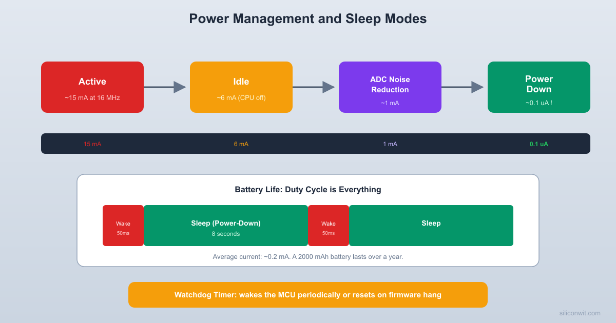
The ATmega328P has six sleep modes, each disabling progressively more hardware to save power. The deeper modes save more current but limit which events can wake the CPU.
The deeper the sleep, the fewer wake sources are available and the longer it takes to resume execution. Power-down mode disables everything except the external interrupt logic and the watchdog timer, achieving the lowest possible current draw.
Sleep Mode
Current (typical)
What Stays Running
Wake Sources
Idle
~3 mA
All clocks, all peripherals
Any interrupt
ADC Noise Reduction
~1 mA
ADC, Timer2 (async), ext. interrupts
ADC complete, ext. int, Timer2, PCINT
Power-save
~1 uA
Timer2 (async), ext. interrupts
Timer2, ext. int, PCINT
Power-down
~0.1 uA
External interrupts only
INT0, INT1, PCINT, TWI address match
Standby
~0.2 uA
Main oscillator, ext. interrupts
Same as power-down (faster wake)
Extended Standby
~0.2 uA
Main osc, Timer2 (async)
Timer2 + power-down sources
Entering Sleep Mode
#include<avr/sleep.h>
/* Select sleep mode */
set_sleep_mode(SLEEP_MODE_PWR_DOWN);
/* Enable sleep, enter sleep, disable sleep after waking */
sleep_enable();
sei(); /* Interrupts must be enabled to wake */
sleep_cpu(); /* CPU halts here until interrupt */
sleep_disable();
Reducing Power Consumption
Getting to sub-microamp sleep current requires more than just calling sleep_mode(). You need to disable every peripheral that draws current in the background. The PRR (Power Reduction Register) lets you shut down individual peripherals. The ADC has its own enable bit that should be cleared before sleeping. BOD (Brown-Out Detection) can be disabled during sleep to save another 15 to 20 microamps.
Power Reduction Checklist
Disable the ADC before sleeping:
ADCSRA &=~(1<< ADEN);
Shut down unused peripherals via PRR:
PRR = (1<< PRTWI) | (1<< PRTIM2) | (1<< PRTIM0)
| (1<< PRTIM1) | (1<< PRSPI) | (1<< PRUSART0)
| (1<< PRADC);
Set all unused pins as inputs with pull-ups enabled (prevents floating pins from drawing current):
DDRB =0x00; PORTB =0xFF;
DDRC =0x00; PORTC =0xFF;
DDRD =0x00; PORTD =0xFF;
Disable the analog comparator:
ACSR |= (1<< ACD);
Disable BOD during sleep (must be done in a timed sequence):
MCUCR |= (1<< BODS) | (1<< BODSE);
MCUCR = (MCUCR &~(1<< BODSE)) | (1<< BODS);
sleep_cpu(); /* Must enter sleep within 3 clock cycles */
Watchdog Timer
The door alert firmware spends nearly all its time asleep, waking only on two events. The watchdog provides a periodic heartbeat, while INT0 signals an immediate alarm condition.
The watchdog timer (WDT) has two uses: as a safety mechanism that resets the chip if the firmware hangs, and as a periodic wakeup source during sleep. It runs from a separate 128 kHz internal oscillator that operates independently of the main clock. The WDT can be configured with timeout periods from 16 ms to 8 seconds.
Watchdog Timeout Periods
WDP3
WDP2
WDP1
WDP0
Timeout
0
0
0
0
16 ms
0
0
0
1
32 ms
0
0
1
0
64 ms
0
0
1
1
125 ms
0
1
0
0
250 ms
0
1
0
1
500 ms
0
1
1
0
1 s
0
1
1
1
2 s
1
0
0
0
4 s
1
0
0
1
8 s
Configuring WDT for Interrupt (Not Reset)
By default, the watchdog resets the chip on timeout. For a periodic wakeup, you configure it to fire an interrupt instead. Setting WDIE (Watchdog Interrupt Enable) in WDTCSR makes the WDT generate an interrupt on timeout. The interrupt clears WDIE automatically, so you must re-enable it before each sleep cycle.
#include<avr/wdt.h>
staticvoidwdt_setup_interrupt_8s(void)
{
cli();
wdt_reset();
/* Timed sequence to change WDT configuration */
WDTCSR |= (1<< WDCE) | (1<< WDE);
/* Interrupt mode, 8s timeout (WDP3=1, WDP0=1) */
WDTCSR = (1<< WDIE) | (1<< WDP3) | (1<< WDP0);
sei();
}
ISR(WDT_vect)
{
/* Watchdog fired. WDIE is auto-cleared. */
/* Re-enable for next cycle in main loop */
}
Reed Switch Wiring
The standalone ATmega328P circuit runs from two AA batteries with minimal external components. No crystal is needed because the internal 8 MHz oscillator provides the clock.
  Standalone ATmega328P circuit:
       2x AA (3V)        +  -        |  |  +-----+--+---------+  | VCC    GND        |  |                   |  |   ATmega328P-PU   |  |                   |  |  PB0---[220R]---[LED]---GND  |  PB1---[Piezo buzzer]---GND  |  PD2---[Reed switch]---GND  |                   |  |  VCC---[100nF]---GND (decoupling)  |                   |  +-------------------+
  Programming: connect USBasp to  MOSI, MISO, SCK, RESET, VCC, GND
A magnetic reed switch is a glass tube containing two ferromagnetic contacts that close in the presence of a magnet. The normally-closed (NC) type keeps the contacts closed when the magnet is near (door closed) and opens them when the magnet moves away (door opens). Wire one terminal to the MCU pin and the other to ground. Enable the internal pull-up on the MCU pin. When the door is closed, the pin reads low (shorted to ground). When the door opens, the pin goes high (pulled up).
Signal
ATmega328P Pin
Connection
Reed switch
PD2 (INT0) or PB0 (PCINT0)
One terminal to pin, other to GND
Piezo buzzer
PB1 (OC1A)
Buzzer between PB1 and GND
Status LED
PB0
LED with 220R to GND
EEPROM: Persistent Storage Across Power Cycles
Lesson 1 introduced the ATmega328P’s three memory spaces: Flash (program), SRAM (runtime variables), and EEPROM (non-volatile data). Flash and SRAM lose their contents when power is removed (SRAM) or can only be written during programming (Flash). EEPROM retains data through power cycles, making it ideal for storing configuration values, calibration constants, or event counters like our door-open count.
The ATmega328P has 1024 bytes of EEPROM with a rated endurance of 100,000 write cycles per byte. Three registers control access:
Writing a single byte requires a timed sequence: set the address and data, enable the master program bit, then enable the program bit within four clock cycles. The CPU halts for about 3.3 ms during the write. Reading is instant (one clock cycle after setting EERE).
The avr-libc library provides avr/eeprom.h with convenient functions that handle the register sequence for you:
#include<avr/eeprom.h>
/* Read a 16-bit word from EEPROM address 0 */
uint16_t count =eeprom_read_word((uint16_t*)0);
/* Write only if the value changed (saves write cycles) */
eeprom_update_word((uint16_t*)0, count +1);
The eeprom_update_* functions are preferred over eeprom_write_* because they skip the write if the value is already correct, extending EEPROM lifespan. At 10 door events per day, 100,000 write cycles would last over 27 years.
Our door alert will store the total number of door-open events at EEPROM address 0. Each time the reed switch triggers, the firmware increments the counter. On startup, the LED blinks the stored count (modulo 10) so you can check it without UART.
if (door_count ==0xFFFF) door_count =0; /* Fresh EEPROM reads as 0xFF */
uint8_t show = door_count %10;
if (show >0) led_blink(show, 150, 150);
elseled_blink(3, 100, 100); /* No events yet */
while (1) {
enter_deep_sleep();
/* --- Woke up --- */
if (door_opened) {
door_opened =0;
/* Increment and save door count */
door_count++;
eeprom_update_word(EE_DOOR_COUNT, door_count);
/* Sound alarm */
buzzer_beep(2000);
led_blink(3, 200, 200);
/* Wait for door to close (debounce) */
_delay_ms(500);
}
if (wdt_fired) {
wdt_fired =0;
/* Heartbeat blink */
DDRB |= (1<< LED_PIN);
PORTB |= (1<< LED_PIN);
_delay_ms(20);
PORTB &=~(1<< LED_PIN);
DDRB &=~(1<< LED_PIN);
}
}
}
Makefile for This Lesson
This project runs at 8 MHz on the internal oscillator, not 16 MHz like the Nano. Copy your Lesson 1 Makefile and change the clock and programmer settings:
Note the differences from earlier lessons: F_CPU is 8000000UL (not 16000000UL), the programmer is usbasp (not arduino), and there is no -P port or -b baud flag since USBasp uses direct SPI, not serial.
Fuse Settings for Standalone Operation
When running the ATmega328P standalone on batteries, you need fuse settings for the internal 8 MHz oscillator (no external crystal needed). This simplifies the circuit and saves the power that the crystal oscillator draws.
Fuse
Value
Meaning
lfuse
0xE2
Internal 8 MHz RC, 65ms startup, no clock divide
hfuse
0xD9
No bootloader, SPI enabled, EEPROM preserved
efuse
0xFF
BOD disabled (we disable it in software too)
Terminal window
# Program fuses with USBasp
avrdude-cusbasp-pm328p\
-Ulfuse:w:0xE2:m\
-Uhfuse:w:0xD9:m\
-Uefuse:w:0xFF:m
Measuring Power Consumption
To verify your power savings, measure the current with a multimeter in series with the battery. In power-down sleep, expect readings below 1 microamp (you may need a microamp-range meter). In active mode at 3V and 8 MHz, expect around 4 to 5 mA. The ratio between these two values determines your battery life: if the device sleeps 99.99% of the time, the average current is dominated by the sleep current.
Battery Life Estimation
Scenario
Average Current
Battery Life (2500 mAh AA)
Always active (8 MHz, 3V)
5 mA
~21 days
Sleep with 8s heartbeat (20ms active)
~1.5 uA average
Over 10 years (theoretical)
Door opens 10 times/day (2s beep each)
~3 uA average
Over 5 years (theoretical)
Realistic with self-discharge
~3 uA average
1 to 2 years
The limiting factor in most battery-powered projects is the battery’s self-discharge rate (about 5% per year for alkaline), not the circuit’s current draw.
Exercises
Add a “low battery” warning: wake every 30 minutes, read the battery voltage via the internal bandgap reference trick (measure 1.1V bandgap against VCC), and if VCC drops below 2.4V, blink the LED rapidly.
Replace the reed switch with a PIR motion sensor. The sensor’s digital output goes high on motion and can drive INT0 directly.
Add a “reset counter” feature: if the button is held during power-up (reed switch closed), clear the EEPROM counter to zero and confirm with a long LED flash. This lets you start fresh after checking the count.
Measure and compare the sleep current with and without BOD disabled, with and without the analog comparator disabled, and with floating pins vs. pulled-up pins. Document the contribution of each source.
Summary
You now understand every power management feature of the ATmega328P: six sleep modes from Idle to Power-down, the Power Reduction Register, analog comparator disable, BOD disable during sleep, the watchdog timer as both a safety mechanism and a periodic wakeup source, and EEPROM for storing data that survives power cycles. The door alert project demonstrates how a battery-powered device can sleep at sub-microamp levels, wake instantly on an external event, and keep a persistent event log in non-volatile memory. These techniques are essential for any embedded system that runs on batteries, and the principles apply directly to every other microcontroller family you will encounter.
Comments