Every embedded project starts with digital I/O: reading a button, lighting an LED, driving a relay. This lesson sets up STM32CubeIDE for the first time, walks through CubeMX pin configuration, and builds a proximity alarm that combines an ultrasonic distance sensor, a relay module, a buzzer, and a push button with interrupt-driven control. By the end you will have a working alarm system and a project template you can reuse for every lesson in this course. #STM32 #GPIO #Sensors
What We Are Building
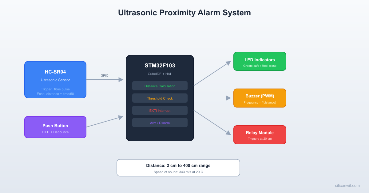
Ultrasonic Proximity Alarm with Relay Trigger
A proximity alarm that measures distance with an HC-SR04 ultrasonic sensor. When an object enters the threshold zone (20 cm), the relay module activates and the buzzer sounds at a frequency proportional to distance. A green LED indicates safe range; a red LED indicates close range. A push button arms and disarms the alarm through an external interrupt, so the system responds instantly regardless of what the main loop is doing.
 HC-SR04 Ultrasonic Timing        10us TRIG:  ┌──┐ ───────┘  └──────────────────────
         8x 40kHz         Echo ECHO:         ┌───────────────┐ ──────────────┘               └──               |<-- t_echo --->|
 Distance = (t_echo * 343 m/s) / 2 1 cm ~ 58 us round-trip
Project specifications:
Parameter
Value
Board
Blue Pill (STM32F103C8T6, WeAct)
System clock
72 MHz (HSE 8 MHz + PLL x9)
HC-SR04 Trigger
PA1 (GPIO Output)
HC-SR04 Echo
PA2 (GPIO Input)
Relay module IN
PA3 (GPIO Output, active low)
Passive buzzer
PA4 (GPIO Output, toggled for tone)
Green LED
PB0 (GPIO Output)
Red LED
PB1 (GPIO Output)
Push button
PB12 (GPIO Input, EXTI12, pull-up)
On-board LED
PC13 (GPIO Output, active low)
Debugger
ST-Link V2 clone over SWD
Bill of Materials
Component
Quantity
Notes
Blue Pill (STM32F103C8T6)
1
WeAct version recommended
ST-Link V2 clone
1
SWD programmer/debugger
HC-SR04 ultrasonic sensor
1
5V sensor, 3.3V compatible echo
Relay module (5V, 1-channel)
1
Opto-isolated, active low input
Passive buzzer
1
Driven by toggling GPIO
Push button (tactile)
1
Normally open
LEDs (green, red)
2
3mm or 5mm
Resistors (330 ohm)
2
LED current limiting
Resistor (10K)
1
External pull-up for button
Breadboard + jumper wires
1 set
Standard full-size breadboard
Setting Up STM32CubeIDE
Why CubeIDE + HAL for This Course
The Embedded Programming: STM32 course used the bare toolchain: arm-none-eabi-gcc, OpenOCD, Makefiles, and direct register access. That approach teaches you what every bit in every register does. For interfacing, the priorities shift. You are wiring multiple external devices, configuring several peripherals at once, and spending most of your time on device driver logic rather than initialization boilerplate. CubeIDE with CubeMX gives you:
Visual pin assignment: select PA1 as GPIO_Output, see conflicts highlighted immediately
HAL code generation: correct initialization sequences from your configuration
Integrated debugger: click-to-set breakpoints, live variable watch, SWV trace
One installation: compiler, debugger, CubeMX, and HAL libraries bundled together
When the bare toolchain is still the right choice: custom bootloaders where you control every byte, safety-critical firmware that must be audited line by line, extremely tight flash constraints where HAL overhead matters (under 8 KB), and CI/CD pipelines where a headless Makefile build is simpler. Both toolchains produce the same ARM binary.
Installing STM32CubeIDE and STM32CubeMX
Starting with version 2.0, STM32CubeIDE no longer bundles CubeMX. You need to install both tools separately.
Step A: Install STM32CubeIDE
Go to st.com/stm32cubeide and click Get Software. ST requires a free account to download. Select the installer for your operating system (Windows, macOS, or Linux).
Windows: Run the .exe installer. Accept the defaults. When prompted, install the ST-Link USB drivers (check the box).
macOS: Open the .dmg, drag STM32CubeIDE to Applications. On first launch, macOS may block it. Go to System Settings > Privacy & Security and click Open Anyway.
Linux (Ubuntu/Debian): Extract the .sh installer and run it:
Terminal window
chmod+xst-stm32cubeide_*.sh
sudo./st-stm32cubeide_*.sh
Accept the license. The installer places the IDE in /opt/st/stm32cubeide_* and creates a desktop shortcut. Install the udev rules when prompted (required for ST-Link access without root).
Verify by launching STM32CubeIDE. It will ask you to select a workspace folder. Create a folder like ~/STM32Projects (or any location you prefer).
Step B: Install STM32CubeMX
Go to st.com/stm32cubemx and click Get Software. Download the installer for your OS.
Windows: Run the .exe installer and accept defaults.
macOS: Open the .dmg and drag to Applications.
Linux: Extract and run the installer:
Terminal window
unzipen.stm32cubemx-lin*.zip
chmod+xSetupSTM32CubeMX-*
sudo./SetupSTM32CubeMX-*
Launch STM32CubeMX to verify:
Windows: Search for “STM32CubeMX” in the Start menu, or run STM32CubeMX.exe from the installation folder.
macOS: Open from Applications, or run from Terminal: open -a STM32CubeMX.
Linux: The installer does not always create a desktop shortcut. Launch from terminal:
On first run it may download firmware packages for your target MCU family (STM32F1 in our case). This requires an internet connection.
Creating a New Project
The workflow is: create and configure the project in CubeMX, generate code, then import it into CubeIDE.
In STM32CubeMX:
Launch STM32CubeMX. On the home screen, click ACCESS TO MCU SELECTOR (or File > New Project).
In the MCU Selector, type STM32F103C8 in the search box. Select STM32F103C8Tx from the filtered list, then click Start Project.
You will see the chip pinout view. This is where you assign every pin before generating code. Configure the peripherals as described in the next section.
After configuring all peripherals, go to the Project Manager tab. Set the project name to ProximityAlarm, choose a project location (create a dedicated subfolder for the project, not the same folder as the CubeIDE workspace), and set Toolchain / IDE to STM32CubeIDE. Click GENERATE CODE. If CubeMX prompts you to download the firmware package (STM32Cube FW_F1), click Yes. This downloads the HAL library for the STM32F1 family and only needs to happen once.
In STM32CubeIDE:
Launch STM32CubeIDE. When it asks for a workspace folder, choose a location that is NOT inside your project folder (e.g., ~/STM32CubeIDE/workspace_2.1.0). The workspace stores CubeIDE’s internal settings; the project folder is separate.
If you see the Information Center welcome screen, close it (click the X on its tab) so you can see the main IDE.
Import the project: go to File > Import, expand General, select Existing Projects into Workspace, click Next. Click Browse next to “Select root directory” and navigate to the project folder that CubeMX generated (e.g., ~/STM32Projects/ProximityAlarm). The project name should appear with a checkbox. Click Finish.
If the Project Explorer is not visible on the left side, go to Window > Show View > Project Explorer. You should see your project with Core/, Drivers/, and the .ioc file.
Build the project by clicking the hammer icon in the toolbar (or Ctrl+B). The Console panel at the bottom shows the build output. You should see “0 errors, 0 warnings” on a fresh CubeMX-generated project.
CubeMX Pin Configuration
You should be on the Pinout & Configuration tab (the default view after creating the project). In the left panel under System Core, click SYS and set Debug to Serial Wire. This reserves PA13 (SWDIO) and PA14 (SWCLK) for the ST-Link.
Still in the left panel under System Core, click RCC and set High Speed Clock (HSE) to Crystal/Ceramic Resonator. Now click the Clock Configuration tab at the top of the window. In the clock tree diagram:
PLL Source Mux: select the HSE radio button (bottom path)
PLLMul: set to x 9 (8 MHz x 9 = 72 MHz)
System Clock Mux: click the PLLCLK radio button (not HSI). SYSCLK should now show 72 MHz.
APB1 Prescaler: set to /2 (APB1 max is 36 MHz)
HCLK should now read 72 MHz.
Go back to the Pinout & Configuration tab. Configure GPIO outputs by clicking each pin on the chip view and selecting GPIO_Output:
PA1: HC-SR04 Trigger
PA3: Relay module
PA4: Buzzer
PB0: Green LED
PB1: Red LED
PC13: On-board LED
Configure GPIO input for Echo: click PA2 and select GPIO_Input.
Configure the push button with EXTI: click PB12 on the chip pinout view and select GPIO_EXTI12 from the dropdown (the pin turns green). Then go to System Core > GPIO in the left panel and click the GPIO Settings tab at the bottom. Click the PB12 row in the list. Set GPIO Pull-up/Pull-down to Pull-up and verify that GPIO mode shows External Interrupt Mode with Falling edge trigger detection (button connects to GND when pressed).
Enable the EXTI interrupt: go to System Core > NVIC and enable EXTI line[15:10] interrupt. Set its priority to 1 (lower than SysTick at 0).
Before generating code, click the Project Manager tab at the top. Verify that Toolchain / IDE is set to STM32CubeIDE (not EWARM or MDK-ARM). Set the project name and location if you have not already. Then click GENERATE CODE (top right corner) or go back to Pinout & Configuration and press Ctrl+S.
Generated Project Structure
DirectoryProximityAlarm/
DirectoryCore/
DirectoryInc/
main.h
stm32f1xx_hal_conf.h
stm32f1xx_it.h
DirectorySrc/
main.c
stm32f1xx_hal_msp.c
stm32f1xx_it.c
system_stm32f1xx.c
DirectoryDrivers/
DirectoryCMSIS/
…
DirectorySTM32F1xx_HAL_Driver/
…
ProximityAlarm.ioc
All your application code goes between the /* USER CODE BEGIN */ and /* USER CODE END */ markers in main.c. CubeMX preserves these sections when you regenerate code after changing pin assignments.
GPIO Output: LEDs, Relay, and Buzzer
Driving an LED
Each GPIO pin on the STM32F103 can source or sink up to 25 mA. A typical LED needs 10 to 20 mA. With a 3.3V output and a 2V forward voltage across the LED, a 330 ohm resistor sets the current to about 4 mA, which is visible and safe.
Most single-channel relay modules are active low: the relay energizes when the input pin is pulled to GND. The module has an optocoupler that isolates the STM32 from the relay coil, and an on-board flyback diode to suppress the inductive spike when the coil de-energizes. The module runs on 5V (from the breadboard supply rail), but the signal input triggers at 3.3V logic levels.
A passive buzzer needs an AC signal to produce sound. Toggling a GPIO pin at a fixed frequency generates a square wave. For a simple alarm, 2 kHz is a good starting point. We will vary the frequency in the final project to indicate distance.
The delay_us function uses the SysTick counter for microsecond delays (defined in the complete code below).
GPIO Input: Push Button with Debouncing
The Bounce Problem
Mechanical switches bounce for 1 to 10 ms after contact. During this window the signal oscillates between high and low many times. Without debouncing, a single press might register as five or ten presses.
Hardware Debouncing
An RC low-pass filter smooths the bounces. Place a 10K resistor in series with the button and a 100 nF capacitor from the GPIO pin to ground. The time constant is R x C = 10K x 100nF = 1 ms, which filters out bounces shorter than about 1 ms. A Schmitt trigger input (which the STM32 GPIO already has) cleans up the slow rising edge that the RC filter produces.
For this project, the STM32’s built-in Schmitt trigger inputs are sufficient when combined with software debouncing.
Software Debouncing
The simplest approach: record the time of the last valid press and ignore any edges within a debounce window (50 ms works well).
Software debounce in interrupt callback
volatileuint32_t last_button_tick =0;
volatileuint8_t alarm_armed =1;
voidHAL_GPIO_EXTI_Callback(uint16_tGPIO_Pin) {
if (GPIO_Pin == GPIO_PIN_12) {
uint32_t now =HAL_GetTick();
if (now - last_button_tick >50) {
alarm_armed =!alarm_armed;
last_button_tick = now;
}
}
}
External Interrupts (EXTI)
Polling a button in the main loop wastes CPU cycles and can miss short presses if the loop is busy. The STM32’s EXTI controller connects each GPIO pin to a dedicated interrupt line. When the pin sees a falling edge (button pressed, pulled to GND), the NVIC fires the interrupt handler immediately.
CubeMX already configured PB12 as EXTI12 with a falling-edge trigger. The generated code in stm32f1xx_it.c calls HAL_GPIO_EXTI_IRQHandler(), which clears the pending flag and calls HAL_GPIO_EXTI_Callback(). You override the callback (shown above) in main.c.
NVIC priority: The STM32F103 uses 4 bits for priority (0 to 15, where 0 is highest). SysTick defaults to priority 0. We set EXTI to priority 1 so it does not preempt the system tick, but still responds faster than any main-loop polling.
HC-SR04 Ultrasonic Sensor
The HC-SR04 measures distance by sending a 40 kHz ultrasonic burst and timing the echo return. The interface is simple:
Send a trigger pulse: drive the Trigger pin HIGH for at least 10 microseconds, then LOW.
Wait for echo: the sensor sets the Echo pin HIGH when the burst leaves and LOW when the echo returns.
Measure the pulse width: the duration of the Echo HIGH pulse, in microseconds, gives the round-trip time.
Calculate distance: distance in cm = (pulse width in us) / 58. This uses the speed of sound at 343 m/s and accounts for the round trip.
Wiring Notes
The HC-SR04 runs on 5V. Its Echo pin outputs a 5V signal, but the pulse width is short and most STM32F103 GPIO pins are 5V tolerant (check the datasheet for “FT” marking on PA2). If you want extra safety, add a voltage divider (1K + 2K) on the Echo line to bring it down to 3.3V.
Microsecond Delay Using SysTick
The HAL provides HAL_Delay() with 1 ms resolution. For the 10 us trigger pulse and echo timing, we need microsecond precision. The DWT (Data Watchpoint and Trace) cycle counter gives us that:
DWT_Init enables the cycle counter for microsecond-accurate timing. This counter runs at the core clock speed (72 MHz) and wraps around every ~59 seconds, which is more than enough for our measurements.
HCSR04_ReadDistance_cm sends a 10 us trigger pulse, measures the echo pulse width using the cycle counter, and converts to centimeters. Timeouts prevent the function from blocking if the sensor is disconnected.
UpdateAlarmOutputs checks the distance against the threshold and drives all outputs accordingly. When disarmed, all outputs turn off and the on-board LED blinks.
HAL_GPIO_EXTI_Callback fires on the falling edge of PB12 (button press). Software debouncing ignores presses within 50 ms of the last valid press. The alarm_armed flag toggles between armed and disarmed states.
The main loop reads the sensor every 100 ms and updates outputs. The HC-SR04 needs at least 60 ms between measurements for reliable readings, so 100 ms is a safe interval.
Production Notes
Moving from Breadboard to PCB
ESD protection on GPIO pins. Any pin connected to an external cable or connector is exposed to electrostatic discharge. Add TVS diodes (e.g., PESD5V0S1BA) on the HC-SR04 echo line and the button input. Cost: a few cents per pin.
Relay flyback diode. The relay module includes a flyback diode on the PCB. If you use a bare relay coil, you must add a 1N4148 diode across the coil (cathode to positive terminal) to absorb the inductive voltage spike when the relay turns off. For more on how diodes work in protection and rectification circuits, see Analog Electronics: Diodes, Rectifiers, and Protection.
Sensor placement. The HC-SR04 has a 15-degree cone angle. Mount it perpendicular to the surface you want to detect. Avoid placing it near walls or corners that create false echoes. The minimum measurable distance is about 2 cm.
Power supply decoupling. Place 100 nF ceramic capacitors close to the VCC pin of every IC and module. The relay module draws a current spike when energizing; if this pulls the 5V rail down, it can cause the STM32 to brown out. A 470 uF electrolytic on the 5V rail helps.
GPIO drive strength. CubeMX defaults to the maximum output speed. For signals that do not need fast edges (LEDs, relay), set the speed to Low. This reduces EMI and ringing on long PCB traces.
Comments