Polling wastes CPU cycles waiting for events that may not happen for seconds or minutes. Interrupts solve this by letting hardware notify the CPU the instant something happens, whether that is a button press, a timer overflow, or a byte arriving over serial. In this lesson you will configure external interrupts, pin-change interrupts, and a timer interrupt to build a reaction time tester. An LED lights up at a random moment, you press a button as fast as you can, and the firmware reports your reaction time in milliseconds over serial. #Interrupts #ISR #EventDriven
What We Are Building
Reaction Time Tester
The firmware waits a random interval (1 to 5 seconds), lights an LED, and starts a millisecond counter driven by Timer1. When you press the button, an external interrupt (INT0) fires, captures the counter value, and sends the result over UART at 9600 baud. False starts (pressing before the LED) are detected and penalized. The entire timing loop is interrupt-driven with no polling in the main loop.
Project specifications:
Parameter
Value
MCU
ATmega328P (on Arduino Nano or Uno)
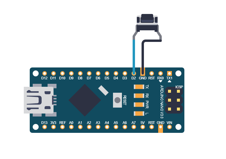
Button interrupt
INT0 (PD2), falling edge
Timer
Timer1, CTC mode, 1 ms tick
LED
PB5 (D13, onboard)
Serial output
9600 baud over USB
Random delay
1000 to 5000 ms (LFSR-based)
Resolution
1 ms
Parts for This Lesson
Ref
Component
Quantity
Notes
1
Arduino Nano or Uno (ATmega328P)
1
From previous lessons
2
Breadboard
1
From previous lessons
3
Push button (tactile)
1
Reuse from Lesson 2
4
Jumper wires
~4
Connect button to PD2
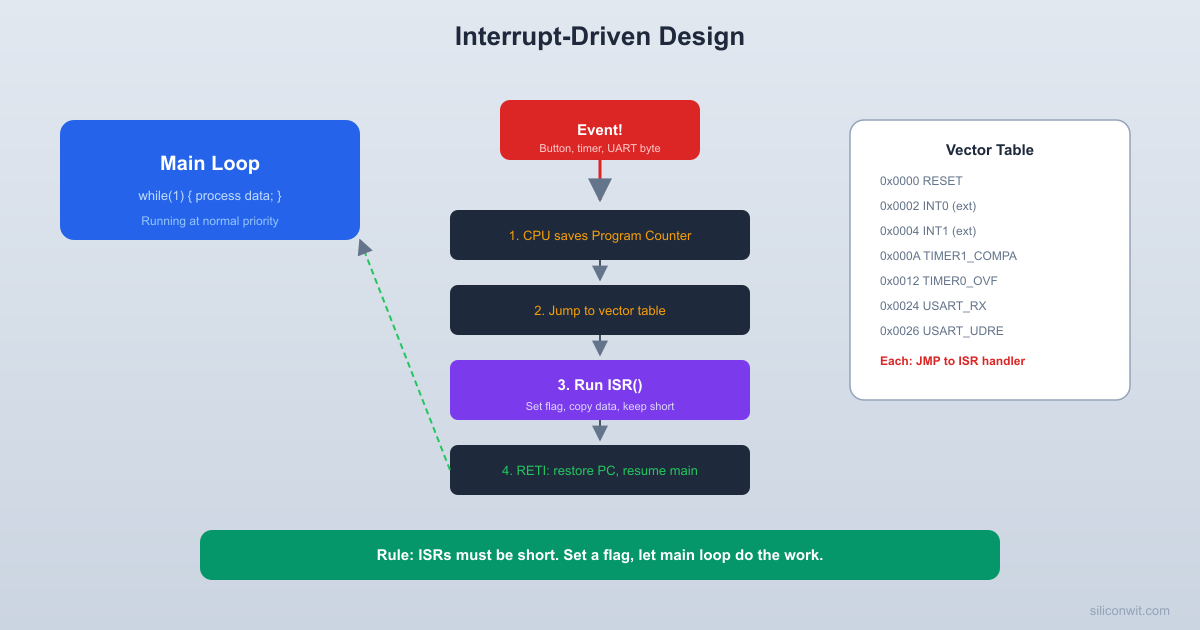
Interrupt Fundamentals
When an interrupt fires, the CPU finishes the current instruction, pushes the program counter onto the stack, disables global interrupts, and jumps to the corresponding interrupt vector.
The interrupt service routine (ISR) executes, then the CPU restores the program counter and re-enables interrupts via the RETI instruction. The entire process takes a minimum of 4 clock cycles for the vector jump alone.
Interrupt Types on ATmega328P
Type
Triggers
Pins
Register
INT0
Rising, falling, low level, any change
PD2
EICRA, EIMSK
INT1
Rising, falling, low level, any change
PD3
EICRA, EIMSK
PCINT0
Any change on PCINT0..7
PB0..PB7
PCICR, PCMSK0
PCINT1
Any change on PCINT8..14
PC0..PC6
PCICR, PCMSK1
PCINT2
Any change on PCINT16..23
PD0..PD7
PCICR, PCMSK2
Timer1 Compare A
TCNT1 matches OCR1A
(internal)
TIMSK1
Timer1 Overflow
TCNT1 overflows
(internal)
TIMSK1
Configuring External Interrupts
The ATmega328P vector table sits at the start of flash. Each entry is a 2-word jump instruction pointing to the handler for that interrupt source.
  ATmega328P Vector Table (partial):
  Address  Vector           Handler  -------  ---------------  ----------------  0x0000   RESET            Reset_Handler  0x0002   INT0             INT0_vect  0x0004   INT1             INT1_vect  0x0006   PCINT0           PCINT0_vect  0x0008   PCINT1           PCINT1_vect  0x000A   PCINT2           PCINT2_vect  0x000C   WDT              WDT_vect  0x000E   TIMER2_COMPA     TIMER2_COMPA_vect   ...      ...              ...  0x0020   TIMER1_COMPA     TIMER1_COMPA_vect   ...      ...              ...  0x0030   USART_RX         USART_RX_vect  0x0032   USART_UDRE       USART_UDRE_vect
INT0 and INT1 are the two dedicated external interrupt pins. You configure the trigger condition in EICRA (External Interrupt Control Register A) and enable the interrupt in EIMSK (External Interrupt Mask Register). The trigger options are: low level (00), any logical change (01), falling edge (10), or rising edge (11). For more on how vector tables, interrupt controllers, and CPU architecture fit together, see Digital Electronics: Microcontroller Architecture Overview.
Writing correct ISRs requires discipline. Keep them short: do the minimum work needed, set a flag, and let the main loop handle the rest. Variables shared between an ISR and main code must be declared volatile so the compiler does not optimize away reads. For multi-byte variables, use atomic blocks to prevent the main code from reading a partially updated value.
#include<avr/interrupt.h>
#include<util/atomic.h>
volatileuint16_t reaction_ms =0;
volatileuint8_t button_flag =0;
ISR(INT0_vect)
{
reaction_ms = TCNT1; /* Capture timer value */
button_flag =1;
}
Timer1 as a Millisecond Counter
For reaction timing, you need a counter that increments every millisecond. Timer1 in CTC mode with prescaler 64 and OCR1A = 249 gives exactly 1 ms per compare match (16000000 / 64 / 250 = 1000 Hz). Instead of using the compare match interrupt to increment a software counter, you can use Normal mode with prescaler 8 and read TCNT1 directly, where each count is 0.5 microseconds. For simplicity, the interrupt-based 1 ms approach is cleaner.
volatileuint16_t ms_counter =0;
voidtimer1_init(void)
{
/* CTC mode, prescaler 64 */
TCCR1A =0;
TCCR1B = (1<< WGM12) | (1<< CS11) | (1<< CS10);
OCR1A =249; /* 1 ms period */
TIMSK1 = (1<< OCIE1A); /* Compare match A interrupt */
}
ISR(TIMER1_COMPA_vect)
{
ms_counter++;
}
Complete Firmware
#defineF_CPU16000000UL
#defineBAUD9600
#defineUBRR_VAL ((F_CPU / (16UL* BAUD)) -1)
#include<avr/io.h>
#include<avr/interrupt.h>
#include<util/delay.h>
#include<util/atomic.h>
#include<stdlib.h>
/* --- UART --- */
staticvoiduart_init(void)
{
UBRR0H = (uint8_t)(UBRR_VAL >>8);
UBRR0L = (uint8_t)(UBRR_VAL);
UCSR0B = (1<< TXEN0);
UCSR0C = (1<< UCSZ01) | (1<< UCSZ00); /* 8N1 */
}
staticvoiduart_putc(charc)
{
while (!(UCSR0A & (1<< UDRE0)));
UDR0 = c;
}
staticvoiduart_puts(constchar*s)
{
while (*s) uart_putc(*s++);
}
staticvoiduart_putu16(uint16_tval)
{
charbuf[6];
utoa(val, buf, 10);
uart_puts(buf);
}
/* --- Timing --- */
volatileuint16_t ms_counter =0;
volatileuint8_t button_flag =0;
ISR(TIMER1_COMPA_vect)
{
ms_counter++;
}
ISR(INT0_vect)
{
button_flag =1;
}
staticvoidtimer1_init(void)
{
TCCR1A =0;
TCCR1B = (1<< WGM12) | (1<< CS11) | (1<< CS10);
OCR1A =249;
TIMSK1 = (1<< OCIE1A);
}
staticuint16_tget_ms(void)
{
uint16_t val;
ATOMIC_BLOCK(ATOMIC_RESTORESTATE) {
val = ms_counter;
}
return val;
}
/* --- LFSR for random delays --- */
staticuint16_t lfsr =0xBEEF;
staticuint16_trandom_delay(void)
{
uint8_t lsb = lfsr &1;
lfsr >>=1;
if (lsb) lfsr ^=0xB400;
return1000+ (lfsr %4001); /* 1000 to 5000 ms */
}
/* --- Main --- */
intmain(void)
{
/* LED on PB5 */
DDRB |= (1<< PB5);
PORTB &=~(1<< PB5);
/* Button on PD2 (INT0), input with pull-up */
DDRD &=~(1<< PD2);
PORTD |= (1<< PD2);
/* INT0: falling edge */
EICRA = (1<< ISC01);
EIMSK = (1<< INT0);
uart_init();
timer1_init();
sei();
uart_puts("Reaction Time Tester\r\n");
uart_puts("Wait for the LED, then press the button!\r\n\r\n");
while (1) {
/* Reset state */
button_flag =0;
PORTB &=~(1<< PB5);
uart_puts("Get ready...\r\n");
/* Random wait */
uint16_t wait =random_delay();
uint16_t start =get_ms();
/* Check for false start during wait */
uint8_t false_start =0;
while ((get_ms()- start) < wait) {
if (button_flag) {
false_start =1;
break;
}
}
if (false_start) {
uart_puts("False start! Wait for the LED.\r\n\r\n");
button_flag =0;
_delay_ms(2000);
continue;
}
/* Light the LED and start timing */
PORTB |= (1<< PB5);
button_flag =0;
uint16_t led_on_time =get_ms();
/* Wait for button press (up to 3 seconds) */
while (!button_flag) {
if ((get_ms()- led_on_time) >3000) break;
}
PORTB &=~(1<< PB5);
if (button_flag) {
uint16_t reaction =get_ms()- led_on_time;
uart_puts("Reaction time: ");
uart_putu16(reaction);
uart_puts(" ms\r\n\r\n");
} else {
uart_puts("Too slow! (over 3 seconds)\r\n\r\n");
}
_delay_ms(2000); /* Pause before next round */
}
}
Pin-Change Interrupts
Pin-change interrupts (PCINTs) are less selective than INT0/INT1: they fire on any logic change (rising or falling) on any enabled pin in their group. You must read the pin state inside the ISR to determine the direction. However, PCINTs cover every single I/O pin on the chip, giving you up to 23 interrupt sources.
When a variable wider than 8 bits is shared between an ISR and main code, the main code might read half the variable, get interrupted, and the ISR updates it, then the main code reads the other half.
This gives a corrupted value. The ATOMIC_BLOCK macro from util/atomic.h temporarily disables interrupts during the read, guaranteeing a consistent value.
#include<util/atomic.h>
volatileuint16_t shared_counter;
/* Safe read from main code */
uint16_tsafe_read(void)
{
uint16_t val;
ATOMIC_BLOCK(ATOMIC_RESTORESTATE) {
val = shared_counter;
}
return val;
}
Exercises
Replace INT0 with a pin-change interrupt on a different pin (for example PB0). You will need to determine edge direction in the ISR by reading the pin state.
Add a “best time” tracker that remembers the fastest reaction across multiple rounds and prints it after each attempt.
Implement a multi-player version: two buttons on INT0 and INT1, and the firmware reports which player reacted first and by how many milliseconds.
Replace the busy-wait random delay with a sleep-based approach: put the CPU in Idle mode and wake it with the timer interrupt. Measure the current difference with a multimeter.
Summary
You now understand how interrupts work on the ATmega328P: vector tables, ISR registration, edge vs. level triggers, and the critical rules for shared variables (volatile, atomic access). You configured INT0 for button input, Timer1 for millisecond counting, and combined them into an event-driven reaction time tester. Interrupt-driven design is fundamental to every serious embedded application, from serial communication to sensor sampling to power management.
Comments