Every electronic circuit, from a simple LED blinker to a complex microcontroller system, operates on three fundamental quantities: voltage, current, and resistance. Understanding how these three relate to each other is the single most important concept in all of electronics. Once you internalize Ohm’s law and Kirchhoff’s laws, you can analyze any circuit you encounter. #AnalogElectronics #OhmsLaw #CircuitFundamentals
The Water Analogy
Before diving into equations, let’s build an intuition using water flow.
Voltage Is Water Pressure
Voltage (measured in volts, V) is the electrical pressure that pushes charges through a circuit. Think of it as the height of a water tank. A higher tank creates more pressure at the bottom. Similarly, a higher voltage creates more force to push current through components.
Current Is Water Flow Rate
Current (measured in amperes, A) is the rate at which electric charge flows through a conductor. It corresponds to the volume of water flowing through a pipe per second. More pressure (voltage) through the same pipe (resistance) means more flow (current).
Resistance Is Pipe Narrowness
Resistance (measured in ohms, ) opposes the flow of current. A narrow pipe restricts water flow. A high-value resistor restricts current flow. Every material has some resistance, and we use resistors to control current deliberately.
This analogy breaks down at advanced levels, but for building circuits on a breadboard, it works remarkably well.
Ohm’s Law
The relationship between voltage, current, and resistance is expressed by Ohm’s law:
Where:
= voltage across the component (volts)
= current through the component (amperes)
= resistance of the component (ohms)
You can rearrange this equation three ways depending on what you need to find:
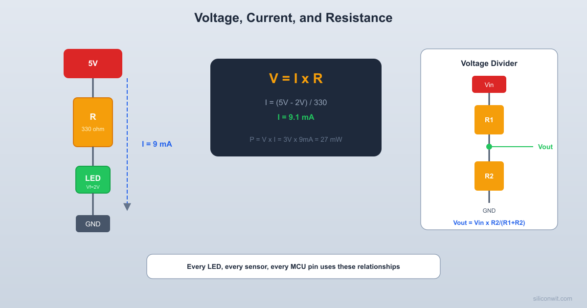
Worked Example: LED Current
Suppose you have a 5V supply and want to drive a red LED. A typical red LED has a forward voltage drop of about 2V and a safe operating current of 20 mA (0.02 A). What resistor do you need?
The resistor must drop the remaining voltage:
Using Ohm’s law to find the resistance:
A standard 150 ohm or 220 ohm resistor will work. Using 220 ohm reduces the current slightly to about 13.6 mA, which is still bright and extends the LED lifetime.
Kirchhoff’s Voltage Law (KVL)
Kirchhoff’s Voltage Law states that the sum of all voltage drops around any closed loop in a circuit equals zero. In practical terms, this means the supply voltage is distributed among all the components in a series circuit.
For a simple series circuit with a battery, resistor, and LED:
This is exactly what we used in the LED example above. The battery provides 5V, the LED drops 2V, and the resistor must drop the remaining 3V. The voltages balance.
Why KVL Matters
KVL lets you find unknown voltages in any loop. If you measure two out of three voltages in a series circuit, KVL tells you the third. When debugging a circuit with a multimeter, KVL is your primary tool: if the voltages around a loop don’t add up, something is wrong (a bad connection, a burned component, or a measurement error).
Kirchhoff’s Current Law (KCL)
Kirchhoff’s Current Law states that the total current entering a node (junction) equals the total current leaving it. No charge is created or destroyed at a junction.
If a wire splits into two branches carrying 10 mA and 15 mA, then 25 mA must be flowing in the wire before the split. This principle is essential when analyzing parallel circuits.
Series and Parallel Resistors
Series Resistors
    VCC     |   [R1]  1K     |   [R2]  2K     |   [R3]  3K     |    GND
  R_total = R1 + R2 + R3 = 6K  Same current through all resistors
Resistors in series carry the same current, and their resistances add:
The voltage divides across them proportionally to their resistance values. A larger resistor drops a larger share of the voltage.
Parallel Resistors
         VCC          |    ┌─────┼─────┐    |     |     |  [R1]  [R2]  [R3]  1K    2K    3K    |     |     |    └─────┼─────┘          |         GND
  Same voltage across all resistors
Resistors in parallel have the same voltage across them, and the total resistance is calculated by:
For two resistors in parallel, there is a convenient shortcut:
Key insight: the parallel combination is always less than the smallest individual resistor. Adding resistors in parallel provides more paths for current, reducing overall resistance.
Quick Reference
Configuration
Same quantity
Adds up
Series
Current
Resistance, Voltage drops
Parallel
Voltage
Current (through each branch)
Power Dissipation
Every resistor converts electrical energy into heat. The power dissipated is:
Power is measured in watts (W). Standard through-hole resistors are rated for 0.25 W (1/4 watt). If your calculation shows a resistor needs to dissipate more than its rating, it will overheat and potentially burn.
Worked Example: Power Check
Using our 150 ohm LED resistor with 20 mA flowing through it:
This is well within the 250 mW rating of a standard 1/4 watt resistor. No problem.
But if you used a 10 ohm resistor to drop 5V directly:
A 1/4 watt resistor would smoke immediately. Always check power dissipation.
The Voltage Divider
A voltage divider is two resistors in series that produce an output voltage that is a fraction of the input voltage. This is one of the most common circuits in all of electronics.
    Vin (5V)      |    [R1]  10K      |      +-----> Vout      |    [R2]  10K      |     GND
  Vout = Vin x R2 / (R1 + R2)       = 5V x 10K / 20K = 2.5V
Where is connected between and , and is connected between and ground.
Worked Example: 3.3V from 5V
To get 3.3V from a 5V source:
Using and :
Close enough. In practice, you might use and for a higher impedance divider that draws less current from the source.
Voltage Divider Limitations
A voltage divider is not a power supply. When you connect a load to the output, the load acts as a resistor in parallel with , changing the output voltage. Voltage dividers work well for:
Reducing a signal level (e.g., 5V logic to 3.3V logic input)
Reading a potentiometer position
Creating a reference voltage for a high-impedance input (like an ADC or op-amp)
They do not work well for powering circuits that draw significant current. Use a voltage regulator for that (see Lesson 6).
Practical Build: Voltage Divider and LED Circuit
Components Needed
Component
Quantity
Notes
Breadboard
1
830 tie-point recommended
5V power source
1
USB power, bench supply, or 4xAA batteries
Resistors: 220, 1k, 2k, 10k ohm
2 each
1/4 watt
LEDs (red)
2
Standard 5mm through-hole
Digital multimeter
1
Measures voltage and current
Jumper wires
Several
Male-to-male for breadboard
Potentiometer (10k ohm)
1
Optional, for variable voltage divider
Circuit 1: LED with Current Limiting Resistor
Connect the power rails
Connect your 5V source to the positive rail and ground to the negative rail on the breadboard.
Place the resistor
Insert a 220 ohm resistor between the positive rail and a breadboard row.
Place the LED
Insert the LED with the anode (longer leg) in the same row as the resistor, and the cathode (shorter leg, flat side) connected to the ground rail.
Power on and observe
The LED should light up. If it does not, check that the LED is not reversed.
Measure the voltage across the resistor
Set your multimeter to DC voltage mode. Place the red probe on the resistor lead closest to the positive rail, and the black probe on the other lead. You should read approximately 3V (since the LED drops about 2V from the 5V supply).
Measure the voltage across the LED
Move the probes across the LED. You should read approximately 2V.
Verify KVL
Add both measurements. They should total approximately 5V (the supply voltage). This is Kirchhoff’s Voltage Law in action.
Measure current
Break the circuit (remove one jumper) and insert the multimeter in series, set to mA mode. You should read approximately 13 to 14 mA with a 220 ohm resistor.
Circuit 2: Voltage Divider
Build the divider
Connect a 1k ohm resistor from the positive rail to a middle row. Connect a 2k ohm resistor from that middle row to ground.
Measure the output
Place your multimeter probes across the 2k resistor (the middle row to ground). You should read approximately 3.33V.
Try different ratios
Swap in different resistor values and predict the output voltage before measuring. Try 10k + 10k (should give 2.5V), or 1k + 10k (should give about 4.55V).
Use a potentiometer
Replace both resistors with a 10k potentiometer. The wiper (center pin) gives you a continuously variable voltage from 0V to 5V as you turn the knob. This is exactly how analog volume controls work.
Verification Checklist
Measurement
Expected Value
Your Measurement
Voltage across 220 ohm resistor (LED circuit)
~3V
________
Voltage across LED
~2V
________
KVL check: sum of drops
~5V
________
Current through LED
~13-14 mA
________
Voltage divider output (1k + 2k)
~3.33V
________
Voltage divider output (10k + 10k)
~2.5V
________
Common Mistakes
Watch Out For These
Forgetting the current limiting resistor on an LED: Without it, the LED draws too much current and burns out instantly. Always calculate the resistor value first.
Mixing up series and parallel formulas: Series adds resistance directly. Parallel uses the reciprocal formula. Double-check which configuration you have.
Ignoring power ratings: A tiny resistor dropping a large voltage at high current will overheat. Always calculate power dissipation.
Using a voltage divider as a power supply: If the load draws significant current, the output voltage drops. Use a voltage regulator instead.
Resistor Color Code Quick Reference
Most through-hole resistors use colored bands to indicate their value. For a 4-band resistor:
When in doubt, use your multimeter to measure the actual resistance. It takes five seconds and eliminates guesswork.
How This Connects to Embedded Systems
You Will Use This Everywhere
Every embedded systems project uses the concepts from this lesson:
GPIO current limits: An STM32 GPIO pin can source about 25 mA. An ATmega328P can source about 20 mA. Ohm’s law tells you what resistor to use with an LED so you stay within these limits.
ADC voltage references: When you read a potentiometer with an ADC, you are reading a voltage divider. Understanding the divider equation lets you convert ADC counts to meaningful values.
Level shifting: A 5V sensor output going into a 3.3V MCU input needs a voltage divider (or a level shifter, which is built from transistors and resistors).
Pull-up and pull-down resistors: I2C buses use pull-up resistors. GPIO buttons use pull-up or pull-down resistors. The resistor value determines the current and the switching speed.
PCB power dissipation: When selecting resistors for a PCB, you need to match the component size (0402, 0603, 0805) to the expected power dissipation.
When you see a 10k pull-up resistor on an I2C bus in a later course, you will understand why 10k was chosen (low enough for reliable communication, high enough to limit wasted current) because you understand Ohm’s law.
Summary
Concept
Key Equation
Remember
Ohm’s Law
Voltage, current, and resistance are always linked
KVL
Voltages around a loop sum to zero
KCL
Current into a node equals current out
Series R
Same current, voltages add
Parallel R
Same voltage, currents add
Power
Always check the watt rating
Voltage Divider
Not a power supply
In the next lesson, we will add capacitors and inductors to the mix, introducing the concept of time-varying behavior that is essential for understanding decoupling, filtering, and timing circuits.
Comments