Register Configuration
Every peripheral setup involves writing hex values to registers. Understanding binary lets you decode what 0x44444443 means for GPIO configuration instead of copying values blindly.
Every microcontroller register, every memory address, and every data byte is a pattern of ones and zeros. When you write PORTB = 0x3F; in C, you are setting six specific bits high and two bits low. This lesson teaches you to think in binary and hexadecimal so that register configurations stop being mysterious hex values and start being clear, intentional bit patterns. #Binary #Hexadecimal #NumberSystems
When you configure a microcontroller, you are writing specific bit patterns to hardware registers. Consider this line of STM32 code:
GPIOA->CRL = 0x44444443;This single hexadecimal value configures eight GPIO pins. Each hex digit (4 bits) controls one pin’s mode and speed. Without understanding hex and binary, this line is opaque. With that understanding, you can read it like a sentence: “Pin 0 is push-pull output at 50 MHz, pins 1 through 7 are floating inputs.”
Every embedded programmer needs three number systems:
| Base | Name | Digits Used | Prefix in C | Common Use |
|---|---|---|---|---|
| 2 | Binary | 0, 1 | 0b | Individual bit manipulation |
| 10 | Decimal | 0-9 | (none) | Human-readable values |
| 16 | Hexadecimal | 0-9, A-F | 0x | Register values, addresses |
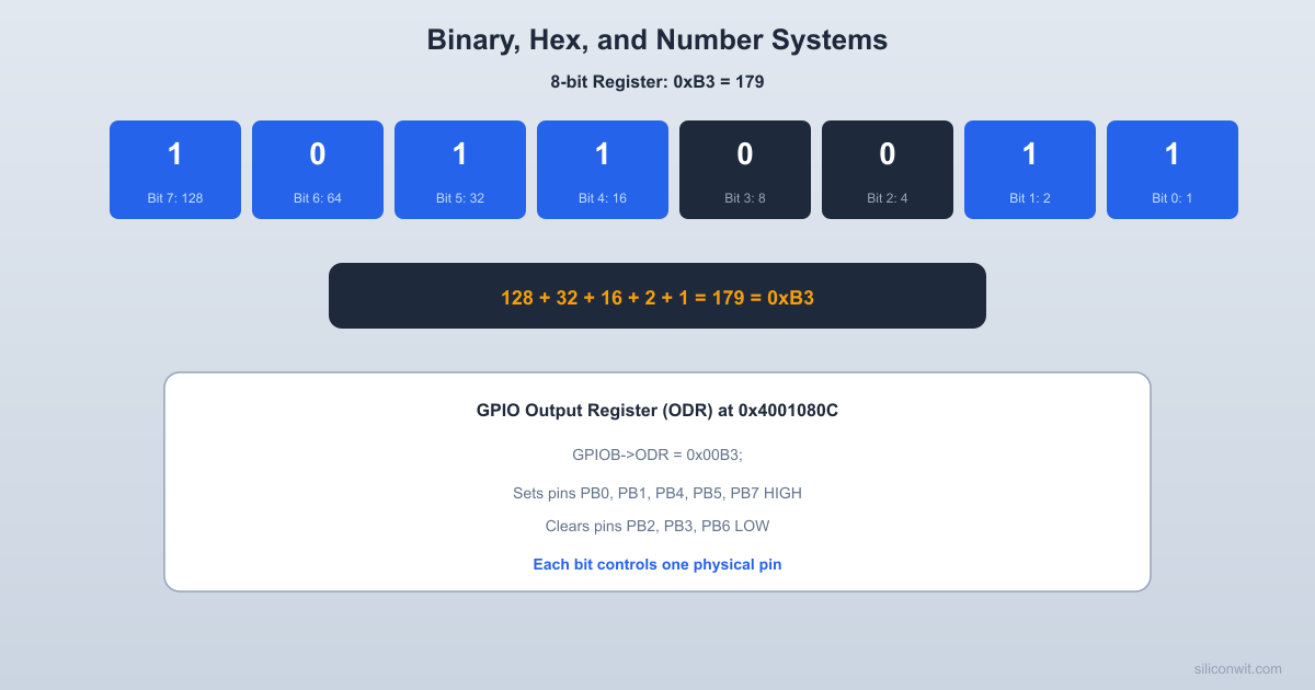
A single binary digit (bit) can be 0 or 1. With more bits, you can represent larger numbers by assigning each position a power of two:
  8-bit Register (one byte)  ┌─────┬─────┬─────┬─────┬─────┬─────┬─────┬─────┐  │ Bit7│ Bit6│ Bit5│ Bit4│ Bit3│ Bit2│ Bit1│ Bit0│  │  1  │  0  │  1  │  1  │  0  │  0  │  1  │  1  │  └─────┴─────┴─────┴─────┴─────┴─────┴─────┴─────┘   128    64    32    16     8     4     2     1   (MSB)                                     (LSB)
Value = 128 + 32 + 16 + 2 + 1 = 179| Bit Position | 7 | 6 | 5 | 4 | 3 | 2 | 1 | 0 |
|---|---|---|---|---|---|---|---|---|
| Weight |
To find the decimal value of a binary number, multiply each bit by its weight and add the results.
Example: 0b10110011
| Decimal | Binary (4-bit) | Decimal | Binary (4-bit) |
|---|---|---|---|
| 0 | 0000 | 8 | 1000 |
| 1 | 0001 | 9 | 1001 |
| 2 | 0010 | 10 | 1010 |
| 3 | 0011 | 11 | 1011 |
| 4 | 0100 | 12 | 1100 |
| 5 | 0101 | 13 | 1101 |
| 6 | 0110 | 14 | 1110 |
| 7 | 0111 | 15 | 1111 |
Notice the pattern: bit 0 toggles every count, bit 1 toggles every 2 counts, bit 2 toggles every 4 counts, and bit 3 toggles every 8 counts. This is exactly how a binary counter circuit works (Lesson 5).
These come up constantly in embedded work:
| Power | Value | Significance |
|---|---|---|
| 256 | One byte range (0 to 255) | |
| 1,024 | 1 KB (kilobyte) | |
| 4,096 | 12-bit ADC range (0 to 4095) | |
| 65,536 | 16-bit timer range, 64 KB | |
| 1,048,576 | 1 MB | |
| 4,294,967,296 | 32-bit address space (4 GB) |
Each memory address holds one byte. Multi-byte values use consecutive addresses:
  Memory layout: 32-bit value 0x12345678
  Address    Byte (little-endian)  ┌────────┬──────────┐  │ 0x1000 │   0x78   │  (LSB stored first)  ├────────┼──────────┤  │ 0x1001 │   0x56   │  ├────────┼──────────┤  │ 0x1002 │   0x34   │  ├────────┼──────────┤  │ 0x1003 │   0x12   │  (MSB stored last)  └────────┴──────────┘
ARM Cortex-M uses little-endian byte order.Example: Convert 179 to binary.
| Step | Division | Quotient | Remainder |
|---|---|---|---|
| 1 | 179 / 2 | 89 | 1 (bit 0) |
| 2 | 89 / 2 | 44 | 1 (bit 1) |
| 3 | 44 / 2 | 22 | 0 (bit 2) |
| 4 | 22 / 2 | 11 | 0 (bit 3) |
| 5 | 11 / 2 | 5 | 1 (bit 4) |
| 6 | 5 / 2 | 2 | 1 (bit 5) |
| 7 | 2 / 2 | 1 | 0 (bit 6) |
| 8 | 1 / 2 | 0 | 1 (bit 7) |
Reading remainders bottom to top: 10110011. Verify:
Binary is precise but verbose. Writing 0b11111111111111111111111111111111 for a 32-bit value is impractical. Hexadecimal solves this by grouping every 4 bits into a single digit:
| Hex Digit | Binary | Decimal |
|---|---|---|
| 0 | 0000 | 0 |
| 1 | 0001 | 1 |
| 2 | 0010 | 2 |
| 3 | 0011 | 3 |
| 4 | 0100 | 4 |
| 5 | 0101 | 5 |
| 6 | 0110 | 6 |
| 7 | 0111 | 7 |
| 8 | 1000 | 8 |
| 9 | 1001 | 9 |
| A | 1010 | 10 |
| B | 1011 | 11 |
| C | 1100 | 12 |
| D | 1101 | 13 |
| E | 1110 | 14 |
| F | 1111 | 15 |
One hex digit = 4 bits. Two hex digits = 8 bits (one byte). Eight hex digits = 32 bits (one word on ARM Cortex-M).
Converting between hex and binary is purely mechanical. Replace each hex digit with its 4-bit binary equivalent:
Example: 0x3F to binary
3 = 0011F = 11110b00111111Example: 0b10110011 to hex
1011 00111011 = B0011 = 30xB3Multiply each hex digit by its positional power of 16:
Example: 0x3F
Example: 0x40021000 (a typical STM32 peripheral base address)
In practice, you almost never convert large hex addresses to decimal. You work in hex because the bit grouping is what matters.
MCU Memory Address Map (simplified) ┌────────────────────────┐ 0xFFFFFFFF │ System / Cortex-M │ ├────────────────────────┤ 0xE0000000 │ (reserved) │ ├────────────────────────┤ 0x40000000 │ Peripheral Regs │ │ (GPIO, UART, SPI...) │ ├────────────────────────┤ 0x20000000 │ SRAM (variables) │ ├────────────────────────┤ 0x08000000 │ Flash (program code) │ └────────────────────────┘ 0x00000000Here is a real example. The STM32F103 GPIO port A configuration register low (GPIOA_CRL) at address 0x40010800 might contain:
GPIOA->CRL = 0x44444443Break it into nibbles (4-bit groups), one per pin:
| Hex Digit | Binary | Pin | Meaning |
|---|---|---|---|
| 3 | 0011 | PA0 | Output, push-pull, 50 MHz |
| 4 | 0100 | PA1 | Floating input |
| 4 | 0100 | PA2 | Floating input |
| 4 | 0100 | PA3 | Floating input |
| 4 | 0100 | PA4 | Floating input |
| 4 | 0100 | PA5 | Floating input |
| 4 | 0100 | PA6 | Floating input |
| 4 | 0100 | PA7 | Floating input |
The least significant hex digit corresponds to the lowest pin number. Each nibble encodes both the mode (input/output) and the configuration (push-pull, open-drain, floating, pull-up/pull-down) for one pin.
BCD encodes each decimal digit separately in 4 bits of binary:
| Decimal | BCD |
|---|---|
| 0 | 0000 |
| 1 | 0001 |
| 2 | 0010 |
| … | … |
| 9 | 1001 |
The combinations 1010 through 1111 are unused in BCD. This wastes some bit patterns, but it makes decimal display straightforward.
Example: Decimal 47 in BCD
010001110100 0111Compare with pure binary: 47 in binary is 00101111. The BCD representation is different because each decimal digit is encoded independently.
BCD is common in:
0x23, that means 23 hours, not decimal 35.// Convert binary to BCD (for values 0-99)uint8_t binary_to_bcd(uint8_t binary) { return ((binary / 10) << 4) | (binary % 10);}
// Convert BCD to binaryuint8_t bcd_to_binary(uint8_t bcd) { return ((bcd >> 4) * 10) + (bcd & 0x0F);}When reading time from an RTC:
uint8_t hours_bcd = rtc_read(RTC_HOURS_REG); // Returns 0x23uint8_t hours = bcd_to_binary(hours_bcd); // Returns 23An 8-bit unsigned integer represents values from 0 to 255. But what about negative numbers? Embedded systems constantly deal with signed values: temperature readings, accelerometer data, motor direction.
Two’s complement is the standard way digital systems represent signed integers. The most significant bit (MSB) becomes the sign bit:
For an 8-bit signed integer:
| Binary | Unsigned Value | Signed Value (Two’s Complement) |
|---|---|---|
| 0111 1111 | 127 | +127 |
| 0000 0001 | 1 | +1 |
| 0000 0000 | 0 | 0 |
| 1111 1111 | 255 | -1 |
| 1111 1110 | 254 | -2 |
| 1000 0001 | 129 | -127 |
| 1000 0000 | 128 | -128 |
An 8-bit signed integer ranges from -128 to +127.
To negate a number in two’s complement:
Example: Find the two’s complement representation of -5.
0000 01011111 10101111 1011Verify: 1111 1011 as a signed byte. The MSB is 1, so it is negative. Invert and add 1 to find the magnitude: invert gives 0000 0100, add 1 gives 0000 0101 = 5. So the original value is -5.
The beauty of two’s complement is that addition works the same for both signed and unsigned numbers. The hardware does not need separate adder circuits:
0000 0011 (+3)+ 1111 1011 (-5)----------- 1111 1110 (-2) ✓The carry out of the MSB is simply discarded. This is why the ALU inside your microcontroller uses a single adder for both signed and unsigned arithmetic.
In C, int8_t is a signed 8-bit type and uint8_t is unsigned. The same bit pattern is interpreted differently:
uint8_t a = 0xFB;   // Unsigned: 251int8_t  b = 0xFB;   // Signed: -5 (same bits, different interpretation)
printf("Unsigned: %u\n", a);  // Prints 251printf("Signed: %d\n", b);    // Prints -5
This matters when reading sensor data. An accelerometer might return a signed 16-bit value where 0xFFE0 means -32, not 65,504.
  Two's complement number line (4-bit)
-8 -7 -6 -5 -4 -3 -2 -1 0 +1 +2 +3 +4 +5 +6 +7 1000 1001 1010 1011 1100 1101 1110 1111 0000 0001 0010 0011 0100 0101 0110 0111 │ │ │ Most Zero Most negative positiveWhen you move a signed value from a smaller type to a larger type, the sign bit must be replicated into the upper bits. This is called sign extension:
int8_t small = -5; // 0xFB = 1111 1011int16_t large = small; // 0xFFFB = 1111 1111 1111 1011The compiler handles this automatically when you assign between signed types, but you need to be aware of it when doing manual bit manipulation.
These operators work on individual bits and map directly to logic gates (Lesson 2):
| Operator | Name | Example | Result | Gate Equivalent |
|---|---|---|---|---|
& | AND | 0xF0 & 0x3C | 0x30 | AND gate |
| | OR | 0xF0 | 0x3C | 0xFC | OR gate |
^ | XOR | 0xF0 ^ 0x3C | 0xCC | XOR gate |
~ | NOT | ~0xF0 | 0x0F | NOT gate (inverter) |
<< | Left shift | 0x01 << 3 | 0x08 | Shift register |
>> | Right shift | 0x80 >> 3 | 0x10 | Shift register |
These patterns appear in virtually every embedded program:
Set a bit (turn it to 1 without changing other bits):
PORTB |= (1 << 5); // Set bit 5 of PORTBClear a bit (turn it to 0 without changing other bits):
PORTB &= ~(1 << 5); // Clear bit 5 of PORTBToggle a bit (flip its value):
PORTB ^= (1 << 5); // Toggle bit 5 of PORTBCheck a bit (test if it is set):
if (PINB & (1 << 5)) { // Bit 5 is high}Set multiple bits using a mask:
// Set bits 0, 1, and 5 of a control registerCTRL_REG |= (1 << 0) | (1 << 1) | (1 << 5); // 0x23Clear a field and set a new value:
// Set timer prescaler bits [2:0] to value 5, without changing other bitsTCCR0B = (TCCR0B & ~0x07) | 0x05; Bit manipulation: set bit 5 of PORTB
Before: PORTB = 0xC1 ┌───┬───┬───┬───┬───┬───┬───┬───┐ │ 1 │ 1 │ 0 │ 0 │ 0 │ 0 │ 0 │ 1 │ └───┴───┴───┴───┴───┴───┴───┴───┘ 7 6 5 4 3 2 1 0
Mask: (1 << 5) = 0x20 ┌───┬───┬───┬───┬───┬───┬───┬───┐ │ 0 │ 0 │ 1 │ 0 │ 0 │ 0 │ 0 │ 0 │ └───┴───┴───┴───┴───┴───┴───┴───┘
After: PORTB |= (1 << 5) => 0xE1 ┌───┬───┬───┬───┬───┬───┬───┬───┐ │ 1 │ 1 │ 1 │ 0 │ 0 │ 0 │ 0 │ 1 │ └───┴───┴───┴───┴───┴───┴───┴───┘This pattern (mask then set) is the most important bit manipulation idiom in embedded programming. You will use it hundreds of times.
Fill in the missing values:
| Decimal | Binary (8-bit) | Hexadecimal |
|---|---|---|
| 42 | ? | ? |
| ? | 1010 1010 | ? |
| ? | ? | 0x7F |
| 200 | ? | ? |
| ? | 0110 0100 | ? |
| Decimal | Binary (8-bit) | Hexadecimal |
|---|---|---|
| 42 | 0010 1010 | 0x2A |
| 170 | 1010 1010 | 0xAA |
| 127 | 0111 1111 | 0x7F |
| 200 | 1100 1000 | 0xC8 |
| 100 | 0110 0100 | 0x64 |
Find the 8-bit two’s complement representation of these signed values:
0000 0001 to 1111 1110, add 1 = 1111 1111 = 0xFF1000 0000 = 0x80 (the most negative 8-bit signed value)0010 1010 to 1101 0101, add 1 = 1101 0110 = 0xD60110 0100 to 1001 1011, add 1 = 1001 1100 = 0x9CAn STM32 GPIO output data register (ODR) reads 0x00000A5F. Which pins (0 through 15) are high?
Focus on the lower 16 bits: 0x0A5F
Convert to binary: 0000 1010 0101 1111
Pins that are high (bit = 1):
Pins high: 0, 1, 2, 3, 4, 6, 9, 11.
Write C expressions to:
REG without changing other bits.REG without changing other bits.STATUS is set.DATA as a value from 0 to 15.// 1. Set bits 4 and 7REG |= (1 << 4) | (1 << 7); // or: REG |= 0x90;
// 2. Clear bits 0-3REG &= ~0x0F; // or: REG &= 0xFFFFFFF0;
// 3. Check bit 5if (STATUS & (1 << 5)) { /* bit 5 is set */ }
// 4. Extract bits [7:4]uint8_t value = (DATA >> 4) & 0x0F;Everything in this lesson is directly applicable the moment you touch a microcontroller:
Register Configuration
Every peripheral setup involves writing hex values to registers. Understanding binary lets you decode what 0x44444443 means for GPIO configuration instead of copying values blindly.
Debugging
When you read a register value in a debugger and see 0x0000040D, you need to instantly know which bits are set. That skill starts with fluent binary/hex conversion.
Data Interpretation
Sensor data often arrives as signed integers, BCD values (from RTCs), or multi-byte values that need assembly from individual bytes. Two’s complement and bit shifting are essential.
Efficient Code
Bit manipulation (set, clear, toggle, check) is how you control hardware efficiently. These operations compile to single instructions on most MCUs.
| Concept | Key Takeaway |
|---|---|
| Binary | Every bit is a power of 2. An 8-bit byte holds 0 to 255. |
| Hexadecimal | Each hex digit is 4 bits. Two hex digits make one byte. |
| BCD | Each decimal digit stored as 4 bits. Used in RTCs and displays. |
| Two’s complement | Signed numbers where the MSB is the sign bit. Invert and add 1 to negate. |
| Bit manipulation | AND to clear/test, OR to set, XOR to toggle, shift to position. |
In the next lesson, you will see how these binary values are processed by logic gates, the physical building blocks that perform AND, OR, and NOT operations in hardware.
Comments