Monitoring voltage and current in real time is a fundamental skill for any embedded project, especially battery-powered designs. The STM32’s ADC can continuously scan multiple analog channels and transfer results to memory via DMA without any CPU involvement. In this lesson you will combine that with the analog watchdog, a hardware comparator that fires an interrupt the instant a reading crosses your threshold, so your firmware reacts to dangerous conditions within microseconds. #STM32 #ADC #AnalogWatchdog
What We Are Building
Voltage and Current Monitor with Threshold Alerts
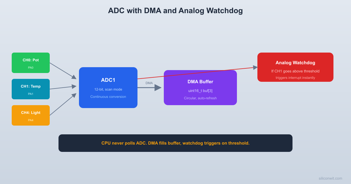
A monitoring system that continuously reads voltage from a potentiometer (ADC channel) and current from an INA219 sensor module (I2C). The ADC runs in continuous scan mode with DMA, reading three channels: the potentiometer voltage, the internal temperature sensor, and the internal voltage reference. The analog watchdog monitors the potentiometer channel and triggers an alert (LED flash + serial warning) when the voltage exceeds a configurable threshold.
The ADC scan mode converts multiple channels in sequence, and DMA transfers each result to memory automatically. The CPU only needs to read the final values from the DMA buffer.
  ADC continuous scan with DMA:
  +------+   +------+   +------+  | CH0  |-->| CH16 |-->| CH17 |--+  | PA0  |   | Temp |   | Vref |  |  +------+   +------+   +------+  |     ^                             |     |          scan repeats       |     +-----------------------------+
  DMA1 Channel 1 transfers:  ADC1->DR --> adc_values[0]  (CH0)  ADC1->DR --> adc_values[1]  (CH16)  ADC1->DR --> adc_values[2]  (CH17)  (circular: restarts automatically)
The STM32F103 has two ADC peripherals (ADC1 and ADC2), each with 12-bit resolution and up to 1 MHz sampling rate. ADC1 has a dedicated DMA channel (DMA1 Channel 1), making it the preferred choice for continuous background conversions. The ADC can convert a sequence of up to 16 channels in a single scan, and in continuous mode it repeats the sequence automatically.
ADC Clock Requirements
The ADC clock must be between 1 MHz and 14 MHz. It is derived from the APB2 clock through a prescaler:
APB2 Clock
Prescaler
ADC Clock
72 MHz
/6
12 MHz
72 MHz
/8
9 MHz
We use /6 for the fastest valid ADC clock (12 MHz).
The analog watchdog is a hardware feature that compares every ADC conversion result against programmable high and low thresholds.
  Analog watchdog operation:
  ADC value  4095 |       |  HTR -+- - - - - - - - - - - - -  HIGH  3000 |                    *       |              *   *   *       |         *  *       *   ALERT!       |    *  *              *       |  *                     *       |*  LTR -+- - - - - - - - - - - - -  LOW   100 |     0 +---+---+---+---+---+----> time           |           |        normal      threshold        range       exceeded:                    AWD interrupt                    fires instantly
When a conversion falls outside the allowed range, it sets a flag and optionally triggers an interrupt. This happens in hardware at ADC speed, so your firmware is notified within one conversion cycle (about 20 us at 12 MHz). Compare this to polling the ADC value in software, which depends on your loop speed and could miss brief spikes entirely.
Watchdog Configuration
#defineAWD_HIGH_THRESHOLD3000 /* ~2.4V at 3.3V reference */
The STM32F103 ADC does not have hardware oversampling (unlike newer STM32 families like the L4 or G4). However, you can implement it in software by averaging multiple samples. Oversampling by 4x and dividing by 2 gives you approximately 1 extra bit of resolution (from 12-bit to ~13-bit effective). Oversampling by 16x and dividing by 4 gives about 2 extra bits. The DMA circular mode makes this easy because the buffer continuously refills.
The INA219 is a high-side current and power monitor with an I2C interface. It measures the tiny voltage drop across a shunt resistor to determine current flow.
  INA219 high-side current measurement:
  V_supply ---+---[R_shunt 0.1R]---+--- Load              |                     |              |  INA219             |              |  +----------+      |              +->| V_IN+    |      |              |  |          |      |              +->| V_IN-    |<-----+                 |          |                 | V_BUS ---+-----> to load                 |          |       I2C <---->| SDA      |       I2C <---->| SCL      |                 +----------+
  Current = V_shunt / R_shunt  INA219 does this calculation  internally and returns mA over I2C.
It measures the voltage drop across a shunt resistor to calculate current, and it also measures the bus voltage. Most INA219 breakout boards include a 0.1 ohm shunt resistor, giving a maximum measurement range of about 3.2A. The INA219 has a built-in 12-bit ADC, so it returns calibrated current and power values directly over I2C.
Comments