On most microcontrollers, peripheral pins are fixed: UART on these two pins, SPI on those four, and if the layout conflicts with your PCB, you redesign the board. The RP2040’s GPIO matrix lets you route almost any peripheral to almost any pin, which means your PCB layout drives your pin assignments, not the other way around. In this lesson you will explore that flexibility along with the PWM slice architecture, the 12-bit SAR ADC, the on-chip temperature sensor, and the hardware interpolators. The project is a potentiometer-controlled LED dimmer with live serial readout of ADC counts, voltage, and die temperature. #GPIO #PWM #AnalogIO
What We Are Building
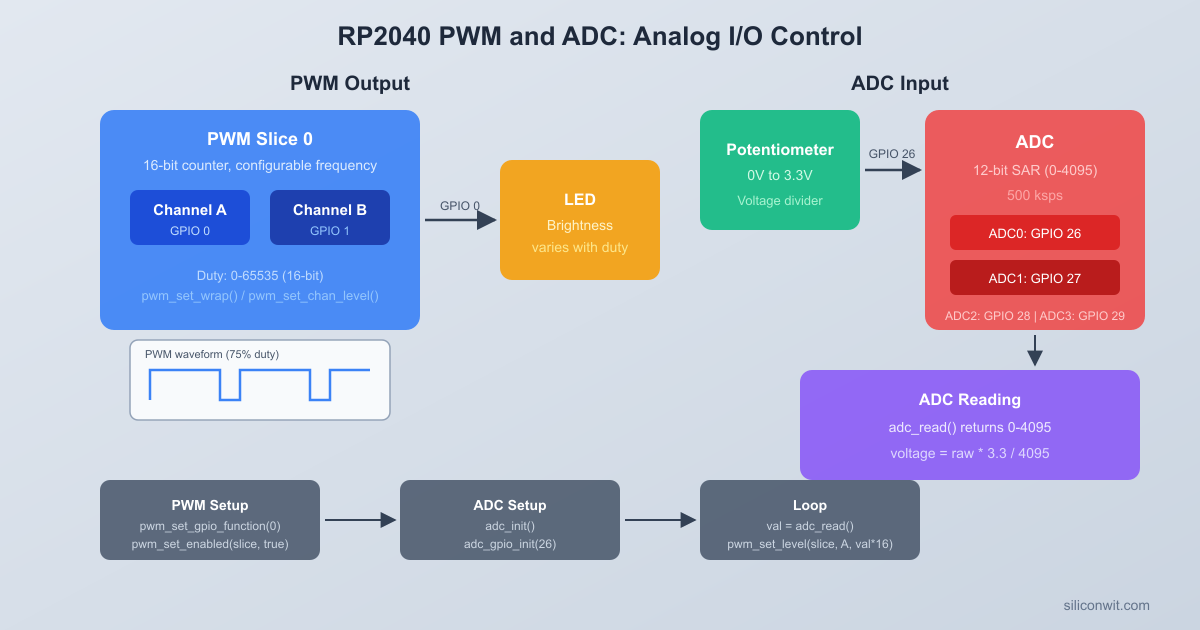
LED Brightness Controller
A potentiometer connected to an ADC input controls LED brightness through PWM. The serial console prints real-time readings: raw ADC counts, voltage, PWM duty cycle percentage, and the RP2040’s on-chip temperature. This simple circuit exercises GPIO configuration, the PWM slice/channel model, and ADC sampling in a single build.
Project specifications:
Parameter
Value
ADC Resolution
12-bit (0-4095)
ADC Input
GP26 (ADC0) for potentiometer
Temperature Sensor
ADC channel 4 (on-chip)
PWM Output
GP15 (Slice 7B)
PWM Frequency
1 kHz
Serial Output
USB CDC at 115200 baud
Supply Voltage
3.3V (from Pico onboard regulator)
Bill of Materials
Ref
Component
Quantity
Notes
1
Raspberry Pi Pico
1
From Lesson 1
2
LED (any color)
2
Standard 3mm or 5mm
3
220 ohm resistor
2
Current limiting for LEDs
4
10K potentiometer
1
Linear taper preferred
5
Breadboard + jumper wires
1 set
GPIO Multiplexing
Every GPIO pin on the RP2040 can serve multiple functions. The chip uses a function select multiplexer (controlled by the IO_BANK0 peripheral) to route each pin to one of several internal peripherals. Only one function can be active on a pin at a time. The Pico SDK provides gpio_set_function() to select which peripheral drives a given pin.
The available functions for each GPIO are:
Function Code
Peripheral
Example Use
GPIO_FUNC_SIO
Software I/O
Digital read/write (default)
GPIO_FUNC_SPI
SPI
Flash, displays, sensors
GPIO_FUNC_UART
UART
Serial console, GPS modules
GPIO_FUNC_I2C
I2C
OLED displays, IMUs, EEPROMs
GPIO_FUNC_PWM
PWM
LED dimming, motor control
GPIO_FUNC_PIO
PIO (Programmable I/O)
Custom protocols, WS2812 LEDs
GPIO_FUNC_USB
USB
USB D+/D- (GP15/GP16 only)
Not every GPIO supports every function. The RP2040 datasheet (Section 2.19.2) contains the full function mapping table. For example, SPI0’s MOSI can appear on GP3, GP7, or GP19, but not on GP0. The SDK will not warn you if you assign an invalid function to a pin; the peripheral simply will not work.
#include"pico/stdlib.h"
#include"hardware/gpio.h"
/* Configure GP15 as a PWM output */
gpio_set_function(15, GPIO_FUNC_PWM);
/* Configure GP0 and GP1 as UART0 TX and RX */
gpio_set_function(0, GPIO_FUNC_UART);
gpio_set_function(1, GPIO_FUNC_UART);
/* Configure GP4 and GP5 as I2C0 SDA and SCL */
gpio_set_function(4, GPIO_FUNC_I2C);
gpio_set_function(5, GPIO_FUNC_I2C);
When a GPIO is set to SIO (the default), you control it directly through the SDK functions gpio_put(), gpio_get(), gpio_set_dir(), and so on. When set to a peripheral function, the peripheral takes over, and SIO calls have no effect on that pin.
Pull-Up and Pull-Down Resistors
Each GPIO has configurable internal pull-up and pull-down resistors (roughly 50K to 80K ohms). These are useful for buttons and open-drain signals:
/* Enable internal pull-up on GP14 (useful for a button to GND) */
gpio_pull_up(14);
/* Enable internal pull-down on GP14 */
gpio_pull_down(14);
/* Disable both pulls */
gpio_disable_pulls(14);
PWM Slice Architecture
The RP2040 has 8 PWM slices, numbered 0 through 7. Each slice contains a 16-bit counter and two output channels, A and B. Both channels in a slice share the same counter and frequency, but each channel has its own independent duty cycle (compare level).
PWM Slice Architecture (1 of 8 slices)
┌──────────────────────────────────────┐
│ Slice N │
│ ┌────────────┐ │
│ │ Clock Div │ │
│ │ (integer + │ │
│ │ fraction) │ │
│ └─────┬──────┘ │
│ v │
│ ┌────────────┐ ┌──────┐ │
│ │ 16-bit │ │ CCR_A│ Channel A
│ │ Counter ├──>│ CMP ├────> GPIO (A)
│ │ 0 to WRAP │ └──────┘ │
│ │ │ ┌──────┐ │
│ │ ├──>│ CCR_B│ Channel B
│ │ │ │ CMP ├────> GPIO (B)
│ └────────────┘ └──────┘ │
│ Same frequency, │
│ independent duty cycles │
└──────────────────────────────────────┘
The mapping from GPIO number to PWM slice and channel is fixed:
GPIO
Slice
Channel
GP0
0
A
GP1
0
B
GP2
1
A
GP3
1
B
GP4
2
A
GP5
2
B
GP6
3
A
GP7
3
B
GP8
4
A
GP9
4
B
GP10
5
A
GP11
5
B
GP12
6
A
GP13
6
B
GP14
7
A
GP15
7
B
The pattern repeats for GP16 through GP29. To find the slice for any GPIO, use pwm_gpio_to_slice_num(gpio). To find the channel, use pwm_gpio_to_channel(gpio).
How the Counter Works
Each PWM slice has a free-running 16-bit counter that counts from 0 up to a configurable wrap value, then resets to 0. The output channel goes high when the counter resets and goes low when the counter reaches the channel’s level (compare value). This produces a PWM waveform where:
Frequency = system clock / (wrap + 1)
Duty cycle = level / (wrap + 1)
The system clock on the Pico defaults to 125 MHz. With a wrap value of 124999, you get a PWM frequency of 1 Hz. With a wrap value of 124, you get 1 MHz. The 16-bit counter limits the wrap value to 65535, giving a minimum frequency of about 1907 Hz at 125 MHz without using the clock divider.
Clock Divider
Each slice also has a fractional clock divider (8 integer bits, 4 fractional bits) that can slow the counter further. The effective frequency becomes:
PWM frequency = system_clock / (divider * (wrap + 1))
For example, to get a 50 Hz PWM for a servo (20 ms period) with full 16-bit resolution:
divider = 125000000 / (50 * 65536) = ~38.15
PWM Configuration
The Pico SDK provides a clean set of functions for configuring PWM. Here is how to set up a 1 kHz PWM on GP15 with a variable duty cycle:
To change the duty cycle at runtime, call pwm_set_chan_level() with a new value between 0 (always off) and wrap+1 (always on).
Frequency Calculation Summary
Desired Freq
Divider
Wrap
Duty Resolution
1 kHz
2.0
62499
62500 steps
10 kHz
1.0
12499
12500 steps
50 Hz (servo)
38.15
65535
65536 steps
100 kHz
1.0
1249
1250 steps
Higher frequencies mean fewer discrete duty cycle steps. At 100 kHz you only have 1250 levels of brightness control. At 1 kHz you have 62500 levels, which is far more than you need for LED dimming.
ADC Architecture
The RP2040 contains a 12-bit successive-approximation register (SAR) ADC capable of 500,000 samples per second. It has 5 input channels:
Channel
Input
Notes
0
GP26 (ADC0)
External analog input
1
GP27 (ADC1)
External analog input
2
GP28 (ADC2)
External analog input
3
GP29 (ADC3)
On Pico: measures VSYS/3
4
Internal
On-chip temperature sensor
The ADC reference voltage is fixed at 3.3V (tied to the ADC_VREF pin on the Pico board). The 12-bit output produces values from 0 to 4095, so the voltage resolution is:
The ADC can be configured to cycle through multiple channels automatically. You specify a bitmask of channels to sample, and the ADC steps through them in order, storing each result in a FIFO. This is useful when you need to sample several inputs continuously without switching channels in software.
#include"hardware/adc.h"
/* Initialize ADC */
adc_init();
/* Configure GP26 and GP27 as ADC inputs */
adc_gpio_init(26);
adc_gpio_init(27);
/* Enable round-robin on channels 0 and 1 */
adc_set_round_robin(0x03); /* Bitmask: bit 0 = ch0, bit 1 = ch1 */
/* Enable FIFO, 1-sample threshold */
adc_fifo_setup(true, false, 1, false, false);
/* Start free-running conversions */
adc_run(true);
On-Chip Temperature Sensor
ADC channel 4 is connected to an internal temperature sensor. The sensor produces a voltage that decreases linearly with temperature. The conversion formula from the RP2040 datasheet is:
T (degrees C) = 27 - (V - 0.706) / 0.001721
Where V is the measured voltage in volts. To get V from the raw ADC reading:
V = raw_adc * (3.3 / 4096)
The temperature sensor is not precision-calibrated. Expect accuracy of roughly plus or minus 2 degrees C. It is useful for monitoring the chip’s own thermal state rather than measuring ambient temperature precisely.
/* Read the on-chip temperature */
adc_set_temp_sensor_enabled(true);
adc_select_input(4);
uint16_t raw =adc_read();
float voltage = raw * (3.3f/4096.0f);
float temperature =27.0f- (voltage -0.706f) /0.001721f;
Circuit Connections
Pico Wiring: ADC + PWM LED
┌──────────────────┐
│ Raspberry Pi │
│ Pico │
│ 3V3 ├─── Pot pin 1
│ │
│ GP26 (ADC0) ├─── Pot wiper (middle)
│ │
│ GND ├─── Pot pin 3
│ │
│ GP15 (PWM 7B) ├──[R1 220R]──┤>├── GND
│ │ LED
│ USB │
└───────┤├─────────┘
Connect the potentiometer and LED to the Pico as follows:
Component
Pico Pin
Connection
Potentiometer wiper (middle pin)
GP26 (ADC0, pin 31)
Analog signal
Potentiometer one outer pin
3V3 (pin 36)
Supply
Potentiometer other outer pin
GND (pin 38)
Ground
LED anode (long leg)
GP15 (pin 20)
Through 220 ohm resistor
LED cathode (short leg)
GND (pin 38)
Ground
The potentiometer forms a voltage divider between 3.3V and GND, producing a voltage from 0V to 3.3V on GP26 as you turn the knob. The LED is driven by PWM on GP15 (Slice 7, Channel B) through a current-limiting 220 ohm resistor.
Complete Firmware
This firmware reads the potentiometer via ADC, maps the 12-bit reading to a PWM duty cycle to control LED brightness, and prints the ADC value, voltage, duty cycle, and chip temperature over USB serial.
#include<stdio.h>
#include"pico/stdlib.h"
#include"hardware/adc.h"
#include"hardware/pwm.h"
#include"hardware/gpio.h"
/* Pin assignments */
#definePOT_PIN26 /* GP26 = ADC0 */
#defineLED_PIN15 /* GP15 = PWM Slice 7, Channel B */
The key difference from Lesson 1’s CMakeLists.txt is the use of hardware_adc and hardware_pwm instead of TinyUSB libraries, and the pico_enable_stdio_usb() call that routes printf() output through a USB CDC (virtual serial port) interface.
Building and Flashing
Create the project directory and copy the SDK import script:
Terminal window
mkdirled-brightness && cdled-brightness
cp$PICO_SDK_PATH/external/pico_sdk_import.cmake.
Create main.c and CMakeLists.txt with the code above, then build:
Terminal window
mkdirbuild && cdbuild
cmake..
make-j$(nproc)
Put the Pico into BOOTSEL mode (hold BOOTSEL, plug in USB, release).
Copy the UF2 to the Pico:
Terminal window
cpled_brightness.uf2/media/$USER/RPI-RP2/
Open a serial monitor to see the output:
Terminal window
# Linux
minicom-b115200-D/dev/ttyACM0
# macOS
screen/dev/cu.usbmodem*115200
# Or use the Arduino Serial Monitor, PuTTY, or any terminal program
Turn the potentiometer knob. The LED brightness should change smoothly, and the serial output should show the ADC reading, voltage, duty cycle, and temperature updating in real time.
Exercises
Add a second LED on GP14 (Slice 7, Channel A). Since GP14 and GP15 share the same PWM slice, both LEDs will run at the same frequency. Set the second LED to the inverse duty cycle (PWM_WRAP - pwm_level) so that one LED brightens while the other dims.
Implement a “breathing” LED effect that ignores the potentiometer. Use a loop that ramps the duty cycle up from 0 to full, then back down, with small steps and short delays. Experiment with linear versus exponential ramping (human eyes perceive brightness logarithmically, so exponential curves look smoother).
Change the ADC sampling to use averaging. Take 16 consecutive readings of channel 0, sum them, and divide by 16 before mapping to PWM. Compare the stability of the serial output with and without averaging, especially at mid-range potentiometer positions.
Log the temperature sensor reading once per second (separate from the 5 Hz ADC loop). Track the minimum and maximum temperatures seen since power-on. Print a summary line every 10 seconds showing current, min, and max temperatures.
Summary
You now understand the three main I/O subsystems of the RP2040. GPIO multiplexing lets any pin serve as SIO, UART, SPI, I2C, PWM, or PIO through a single function select call. The PWM peripheral provides 8 slices with 2 channels each, independent clock dividers, configurable wrap values for frequency control, and per-channel compare levels for duty cycle. The 12-bit SAR ADC offers 5 channels (3 external, VSYS monitor, and on-chip temperature) with round-robin and FIFO modes for continuous sampling. The LED brightness controller project tied all three together: reading an analog voltage, mapping it to a PWM duty cycle, and printing diagnostic data over USB serial.
Comments