Dedicating separate GPIO pins and custom protocols to every peripheral does not scale. With three sensors, a display, and an EEPROM, you would burn through most of the Blue Pill’s I/O just on point-to-point wiring. I2C solves this with a shared two-wire bus where every device has its own address, so five chips share two pins and coexist without conflict. In this lesson you will connect a BME280 environmental sensor, an SSD1306 OLED display, and an AT24C256 EEPROM to a single I2C bus, write drivers for each, and combine them into a weather station that shows live readings, logs history to non-volatile memory, and recalls min/max statistics at the press of a button. #STM32 #I2C #Sensors
What We Are Building
Weather Station with OLED Display and EEPROM Logging
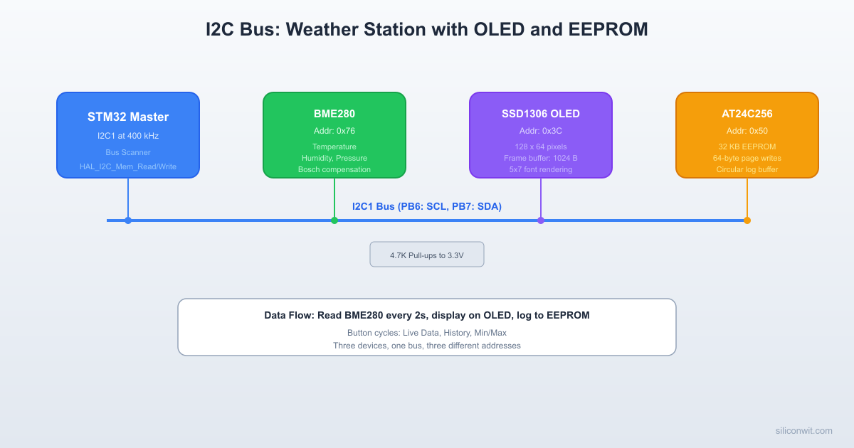
A self-contained weather station that reads temperature, humidity, and barometric pressure from a BME280 sensor every 2 seconds, displays the values on a 128x64 SSD1306 OLED screen, and stores each reading in an AT24C256 EEPROM using a circular buffer. Pressing a button cycles the display between three modes: live data, scrollable log history, and min/max summary. All three devices share the same I2C1 bus.
Project specifications:
Parameter
Value
Board
Blue Pill (STM32F103C8T6)
I2C peripheral
I2C1 (PB6 SCL, PB7 SDA)
I2C speed
400 kHz (Fast mode)
BME280 address
0x76 (SDO pin tied to GND)
SSD1306 address
0x3C (SA0 pin tied to GND)
AT24C256 address
0x50 (A0, A1, A2 all tied to GND)
Pull-up resistors
2.2K on SDA and SCL (for 400 kHz)
Button
PB10 (GPIO input, internal pull-up)
Serial debug
USART1 on PA9/PA10 (115200 baud)
Sensor read interval
2 seconds
EEPROM log capacity
512 entries (8 bytes each, 4 KB used of 32 KB total)
Bill of Materials
Component
Quantity
Notes
Blue Pill (STM32F103C8T6)
1
WeAct version recommended
ST-Link V2 clone
1
SWD programmer/debugger
BME280 module (I2C)
1
GY-BME280 breakout, 3.3V compatible
SSD1306 OLED 128x64 (I2C)
1
4-pin module (VCC, GND, SCL, SDA)
AT24C256 EEPROM module
1
32 KB I2C EEPROM
Pull-up resistors (2.2K)
2
For SDA and SCL lines
Push button
1
Display mode toggle
Breadboard + jumper wires
1 set
Assorted lengths
I2C Protocol Fundamentals
I2C (Inter-Integrated Circuit) uses two open-drain lines: SDA (data) and SCL (clock). The master (STM32) generates the clock and initiates transfers. Multiple slaves share the bus, each responding only to its own address. Because the lines are open-drain, external pull-up resistors are mandatory.
I2C Bus with Three Devices
3.3V
│ │
[2.2K] [2.2K]
│ │
SDA ───────┼─────────┼──────────────
│ │
SCL ───────┼─────────┼──────────────
│ │
┌───────┐ ┌┴───────┐ ┌┴──────────┐
│BME280 │ │SSD1306 │ │AT24C256 │
│ 0x76 │ │ 0x3C │ │ 0x50 │
│Sensor │ │ OLED │ │ EEPROM │
└───────┘ └────────┘ └──────────┘
PB6 = SCL, PB7 = SDA (I2C1)
Signal Timing
 I2C Write Transaction SCL: ──┐ ┌─┐ ┌─┐ ┌─┐ ┌─┐ ┌─┐ ┌─┐ ┌─┐ ┌─┐ ┌──        └─┘ └─┘ └─┘ └─┘ └─┘ └─┘ └─┘ └─┘ └─┘
 SDA: ─┐  A6  A5  A4  A3  A2  A1  A0  W ACK  ┌─       └──┤───┤───┤───┤───┤───┤───┤──┤──┤────┘     START|<-- 7-bit address -->|R/W| |STOP           Slave pulls SDA low ──┘
A transfer begins with a start condition (SDA falls while SCL is high) and ends with a stop condition (SDA rises while SCL is high). Between start and stop, data bits are clocked on SCL edges. Each byte is followed by an ACK bit: the receiver pulls SDA low to acknowledge, or leaves it high (NACK) to signal an error or end of transfer.
7-bit addressing: The first byte after the start condition contains the 7-bit slave address in bits [7:1] and the R/W direction in bit [0]. So address 0x76 becomes 0xEC for a write (0x76 shifted left, OR with 0) and 0xED for a read (0x76 shifted left, OR with 1). The HAL functions handle this shift automatically; you pass the 8-bit shifted address (0x76 << 1 = 0xEC).
Pull-Up Resistor Selection
The pull-up resistor value depends on bus speed and total bus capacitance:
Bus Speed
Typical Pull-Up
Max Bus Capacitance
100 kHz (Standard)
4.7K
400 pF
400 kHz (Fast)
2.2K
400 pF
Lower resistance means faster rise times but higher power consumption. With three devices on a breadboard (roughly 50 to 100 pF total capacitance), 2.2K resistors work well at 400 kHz. Some breakout modules include onboard pull-ups (typically 4.7K or 10K). If multiple modules each have pull-ups, the effective resistance drops too low. Check your modules and remove extra pull-ups by desoldering the resistors or cutting the trace, keeping only one pair of 2.2K pull-ups on the bus.
Clock Stretching
Some slow devices hold SCL low to pause the master while they process data. The STM32 I2C peripheral supports clock stretching by default. The BME280 and AT24C256 both use clock stretching during certain operations.
I2C Device Address Map
Device
7-bit Address
8-bit Write
8-bit Read
Function
BME280
0x76
0xEC
0xED
Temperature, humidity, pressure
SSD1306
0x3C
0x78
0x79
128x64 OLED display
AT24C256
0x50
0xA0
0xA1
32 KB EEPROM storage
CubeMX I2C Configuration
In the Pinout view, enable I2C1. CubeMX assigns PB6 (SCL) and PB7 (SDA) by default. If you need remapped pins (PB8/PB9), enable the AFIO remap in the System Core section.
In the I2C1 Parameter Settings, set I2C Speed Mode to “Fast Mode” and I2C Clock Speed to 400000 (400 kHz). Leave the duty cycle at 2 (16/9 is optional for noise reduction).
Set PB10 as GPIO_Input with internal pull-up (button).
Enable USART1 in asynchronous mode at 115200 baud for debug output.
Generate the project code. CubeMX creates the I2C1 handle (hi2c1) and all initialization code.
Wiring
STM32 Pin
Connects To
Function
PB6
BME280 SCL, SSD1306 SCL, AT24C256 SCL
I2C1 SCL (shared bus)
PB7
BME280 SDA, SSD1306 SDA, AT24C256 SDA
I2C1 SDA (shared bus)
PB10
Push button (other side to GND)
Display mode toggle
PA9
USB-Serial RX
USART1_TX debug
3.3V
BME280 VCC, SSD1306 VCC, AT24C256 VCC
Device power
GND
BME280 GND, SSD1306 GND, AT24C256 GND, button
Common ground
3.3V
2.2K resistor to PB6, 2.2K resistor to PB7
I2C pull-ups
I2C Bus Scanner
Before writing device-specific drivers, scan the bus to verify that all devices respond. This is the single most useful I2C debugging tool.
i2c_scan.c
voidi2c_scan(I2C_HandleTypeDef *hi2c)
{
charbuf[64];
uint8_t found =0;
uart_print("I2C bus scan starting...\r\n");
for (uint8_t addr =1; addr <128; addr++)
{
/* HAL_I2C_IsDeviceReady sends the address and checks for ACK */
if (HAL_I2C_IsDeviceReady(hi2c, addr <<1, 1, 10)== HAL_OK)
{
snprintf(buf, sizeof(buf), " Device found at 0x%02X\r\n", addr);
If a device does not appear, check wiring, pull-ups, and power supply. If no devices appear at all, the I2C peripheral may not be initialized or the pins may be misconfigured.
BME280 Sensor Driver
The BME280 measures temperature, pressure, and humidity. Bosch provides compensation formulas in the datasheet that convert raw ADC values to calibrated readings. The calibration coefficients are unique to each sensor and stored in the device’s non-volatile memory.
BME280 Register Map (Key Registers)
Register
Address
Description
chip_id
0xD0
Returns 0x60 for BME280, 0x58 for BMP280
ctrl_hum
0xF2
Humidity oversampling
ctrl_meas
0xF4
Temperature/pressure oversampling, mode
config
0xF5
Standby time, IIR filter, SPI enable
calib00..calib25
0x88..0xA1
Temperature and pressure calibration
calib26..calib41
0xE1..0xF0
Humidity calibration
press_msb..hum_lsb
0xF7..0xFE
Raw measurement data (8 bytes)
Driver Header
bme280.h
#ifndefBME280_H
#defineBME280_H
#include"stm32f1xx_hal.h"
#defineBME280_ADDR (0x76<<1)
#defineBME280_CHIP_ID0x60
#defineBME280_REG_ID0xD0
#defineBME280_REG_RESET0xE0
#defineBME280_REG_CTRL_HUM0xF2
#defineBME280_REG_CTRL_MEAS0xF4
#defineBME280_REG_CONFIG0xF5
#defineBME280_REG_DATA0xF7
#defineBME280_REG_CALIB_T0x88
#defineBME280_REG_CALIB_H0xE1
typedefstruct {
/* Temperature calibration */
uint16_t dig_T1;
int16_t dig_T2;
int16_t dig_T3;
/* Pressure calibration */
uint16_t dig_P1;
int16_t dig_P2;
int16_t dig_P3;
int16_t dig_P4;
int16_t dig_P5;
int16_t dig_P6;
int16_t dig_P7;
int16_t dig_P8;
int16_t dig_P9;
/* Humidity calibration */
uint8_t dig_H1;
int16_t dig_H2;
uint8_t dig_H3;
int16_t dig_H4;
int16_t dig_H5;
int8_t dig_H6;
} BME280_Calib;
typedefstruct {
I2C_HandleTypeDef *hi2c;
BME280_Calib calib;
int32_t t_fine; /* Shared between temperature and pressure compensation */
The SSD1306 is a 128x64 monochrome OLED controller. It stores pixel data in a 1024-byte frame buffer organized as 8 pages of 128 columns, where each byte represents 8 vertical pixels. To update the display, you write the entire frame buffer (or a portion of it) over I2C.
SSD1306 I2C Protocol
I2C communication with the SSD1306 uses a control byte before each data byte (or data block):
The AT24C256 is a 32 KB I2C EEPROM organized in 64-byte pages. Key characteristics:
Parameter
Value
Total capacity
32,768 bytes (256 Kbit)
Page size
64 bytes
Address size
2 bytes (16-bit internal address)
Write cycle time
5 ms maximum
Endurance
1,000,000 write cycles per page
Write cycle time is the critical constraint. After writing a byte or page, you must wait at least 5 ms before the next write operation. The HAL write function returns immediately, but the EEPROM is internally busy. You can either wait 5 ms (simple) or poll the device with HAL_I2C_IsDeviceReady() until it ACKs (faster, called “acknowledge polling”).
Page boundary handling: A page write wraps within the 64-byte page boundary. If you start writing at byte 60 within a page and send 10 bytes, only the first 4 bytes land at addresses 60 to 63; the remaining 6 bytes wrap around to addresses 0 to 5 within the same page, overwriting existing data. To write across page boundaries, split the write into multiple page-aligned transactions.
The main application ties all three devices together. Sensor readings are taken every 2 seconds, displayed on the OLED, and logged to EEPROM. A button cycles through three display modes.
main.c
/* USER CODE BEGIN Includes */
#include<stdio.h>
#include<string.h>
#include"bme280.h"
#include"ssd1306.h"
#include"eeprom.h"
/* USER CODE END Includes */
/* USER CODE BEGIN PV */
/* Display modes */
#defineMODE_LIVE0
#defineMODE_HISTORY1
#defineMODE_MINMAX2
/* EEPROM log layout:
* Bytes 0..3: header (write index as uint16_t, entry count as uint16_t)
* Bytes 4..4099: circular buffer, 512 entries x 8 bytes each
if (HAL_GPIO_ReadPin(GPIOB, GPIO_PIN_10)== GPIO_PIN_RESET)
{
last_btn_tick = now;
if (display_mode == MODE_HISTORY)
{
/* In history mode, button advances page; long gap resets to live */
uint16_t max_pages = (log_count +3) /4;
history_page++;
if (history_page >= max_pages)
{
history_page =0;
display_mode = MODE_MINMAX;
}
}
else
{
display_mode = (display_mode +1) %3;
history_page =0;
}
}
}
/* USER CODE END 0 */
main.c (continued: main loop)
/* USER CODE BEGIN 2 */
uart_print("I2C Weather Station starting...\r\n");
/* Scan bus first */
i2c_scan(&hi2c1);
/* Initialize BME280 */
if (BME280_Init(&bme280, &hi2c1) != HAL_OK)
{
uart_print("ERROR: BME280 init failed\r\n");
/* Continue anyway; display will show zeros */
}
else
{
uart_print("BME280 initialized (chip ID 0x60)\r\n");
}
/* Initialize OLED */
if (SSD1306_Init(&oled, &hi2c1) != HAL_OK)
{
uart_print("ERROR: SSD1306 init failed\r\n");
}
else
{
uart_print("SSD1306 OLED initialized\r\n");
}
/* Load EEPROM log header */
load_log_header();
snprintf(uart_buf, sizeof(uart_buf),
"EEPROM log: %u entries, write index %u\r\n",
log_count, log_write_idx);
uart_print(uart_buf);
/* Show splash screen */
SSD1306_Clear(&oled);
SSD1306_WriteString(&oled, 10, 20, "WEATHER", 2);
SSD1306_WriteString(&oled, 10, 42, "STATION", 2);
SSD1306_Update(&oled);
HAL_Delay(1500);
/* USER CODE END 2 */
/* Infinite loop */
/* USER CODE BEGIN WHILE */
uint32_t last_read_tick =0;
while (1)
{
uint32_t now =HAL_GetTick();
/* Read sensor every 2 seconds */
if ((now - last_read_tick) >=2000)
{
last_read_tick = now;
if (BME280_Read(&bme280, &sensor_data)== HAL_OK)
{
update_minmax(&sensor_data);
log_reading(&sensor_data);
snprintf(uart_buf, sizeof(uart_buf),
"T=%.1fC H=%.1f%% P=%.1fhPa\r\n",
sensor_data.temperature,
sensor_data.humidity,
sensor_data.pressure);
uart_print(uart_buf);
}
else
{
uart_print("BME280 read error\r\n");
}
/* Update display in current mode */
if (display_mode == MODE_LIVE)
display_live(&sensor_data);
}
/* Handle button (checked every loop iteration) */
handle_button();
/* Refresh non-live displays when mode changes */
staticuint8_t prev_mode = MODE_LIVE;
staticuint8_t prev_page =0;
if (display_mode != prev_mode || history_page != prev_page)
{
prev_mode = display_mode;
prev_page = history_page;
switch (display_mode)
{
case MODE_LIVE: display_live(&sensor_data); break;
case MODE_HISTORY: display_history(); break;
case MODE_MINMAX: display_minmax(); break;
}
}
HAL_Delay(10);
/* USER CODE END WHILE */
/* USER CODE BEGIN 3 */
}
/* USER CODE END 3 */
Linker note: STM32CubeIDE uses newlib-nano by default, which disables float formatting in printf/snprintf. To enable %.1f, go to Project Properties, C/C++ Build, Settings, MCU GCC Linker, Miscellaneous, and add -u _printf_float to Other flags. The integer-based OLED formatting above avoids this requirement.
CubeIDE Project Structure
Directoryi2c_weather_station/
DirectoryCore/
DirectoryInc/
main.h
bme280.h
ssd1306.h
eeprom.h
stm32f1xx_hal_conf.h
stm32f1xx_it.h
DirectorySrc/
main.c
bme280.c
ssd1306.c
eeprom.c
stm32f1xx_hal_msp.c
stm32f1xx_it.c
system_stm32f1xx.c
DirectoryDrivers/
DirectoryCMSIS/
…
DirectorySTM32F1xx_HAL_Driver/
…
i2c_weather_station.ioc
Testing and Verification
Run the I2C scanner first. Flash the project, open a serial terminal at 115200 baud, and verify that all three devices (0x3C, 0x50, 0x76) appear. If a device is missing, check its wiring and power before proceeding.
Verify BME280 readings. Compare the temperature reading against a known thermometer. The BME280 self-heats by roughly 1 to 2 degrees Celsius when running continuously; this is normal and documented in the datasheet. Humidity and pressure should be reasonable for your location (sea level pressure is approximately 1013 hPa).
Test the OLED display. The splash screen should appear for 1.5 seconds, then live readings update every 2 seconds. If the display shows garbled content, check the I2C address (some modules use 0x3D instead of 0x3C) and verify the initialization sequence.
Test EEPROM logging. Let the station run for a minute (30 entries), then press the button twice to reach history mode. You should see logged entries with temperature and humidity values. Power cycle the board and verify that the log persists; the entry count and write index are stored in EEPROM.
Test all display modes. Press the button to cycle: Live, History (multiple pages if enough entries), Min/Max. Verify that min/max values update when you warm the sensor (breathe on it) or cool it.
Production Notes
Pull-up resistor selection. On a breadboard with short wires and three devices, 2.2K pull-ups at 400 kHz work reliably. On a PCB with longer traces or more devices, measure the bus capacitance with an oscilloscope: the SCL rise time should be under 300 ns for Fast mode. If rise times are too slow, reduce the pull-up resistance (minimum 1K for 3.3V logic to stay within the 3 mA sink current spec).
Bus capacitance. Each I2C device adds roughly 10 pF of input capacitance. The PCB traces add about 1 to 2 pF per centimeter. The I2C specification limits total bus capacitance to 400 pF. On a breadboard you are well within this limit, but on a product with long ribbon cables to remote sensors, you may need an I2C bus extender (such as the PCA9600) or slower bus speed.
Level shifting for 5V devices. The BME280 and SSD1306 are 3.3V devices and connect directly to the STM32. Some EEPROM modules are 5V. If your AT24C256 module runs at 5V, use a bidirectional level shifter (such as the BSS138 MOSFET circuit) between the STM32 and the module. Never connect a 5V I2C pull-up directly to the STM32; the GPIO pins are not 5V tolerant on all I2C-capable pins (PB6 and PB7 are 5V tolerant on the F103, but relying on this is risky for production).
BME280 self-heating. In forced mode, the sensor powers down between measurements and self-heating is negligible. In normal mode (used here for convenience), the sensor self-heats by 1 to 2 degrees Celsius. For accurate temperature readings in a product, use forced mode: write the mode bits in ctrl_meas to 01 or 10 (forced), trigger a single measurement, read the result, then the sensor returns to sleep automatically.
EEPROM write endurance. The AT24C256 is rated for 1,000,000 write cycles per page. At one write every 2 seconds, a single page would wear out in about 23 days. The circular buffer in this project distributes writes across 64 pages (4 KB / 64 bytes per page), extending the effective lifetime to roughly 4 years of continuous operation. For longer lifetimes, use a larger portion of the EEPROM or implement wear leveling.
I2C error recovery. If a slave device holds SDA low (bus lockup), the master cannot issue a start condition. The standard recovery procedure is to toggle SCL manually (9 clock pulses) to force the slave to release SDA. The STM32 HAL does not do this automatically. For robust firmware, implement a bus recovery function that temporarily reconfigures PB6 as GPIO output, sends 9 clock pulses, then reconfigures it as I2C SCL.
Comments