Every embedded product eventually needs to run on batteries. The difference between firmware that drains a CR2032 in a week and firmware that runs for a year comes down to understanding sleep modes, wakeup sources, and peripheral power management. In this final lesson you will build a data logger that spends 99.9% of its time asleep, waking briefly to read a sensor, write to SPI flash, and go back to sleep. You will also learn the production firmware essentials: flash programming, option bytes, read protection, and bootloader basics. #STM32 #LowPower #Production
What We Are Building
Battery-Powered Data Logger
A self-contained data logger powered by a CR2032 coin cell (3V, ~220 mAh). The STM32 sleeps in Stop mode between measurements. Every 60 seconds, the RTC alarm wakes the MCU. It reads the BME280 sensor over I2C, writes the timestamped data to a W25Q SPI flash chip, and returns to Stop mode. A serial command (via UART wakeup) lets you dump all logged data to a terminal for retrieval. The target is at least 6 months of operation on a single CR2032.
Project specifications:
Parameter
Value
Board
Blue Pill (STM32F103C8T6)
Power source
CR2032 coin cell (3V, ~220 mAh)
Sleep mode
Stop mode (1.4 uA typical, RTC running)
Wakeup source
RTC Alarm A, every 60 seconds
Sensor
BME280 on I2C1 (forced mode, then sleep)
Storage
W25Q32 SPI flash (4 MB, ~330,000 log entries)
Log entry size
12 bytes (timestamp + temp + pressure + humidity)
Serial interface
USART1 for data retrieval (wakeup on RX activity)
Target battery life
6+ months on CR2032
Bill of Materials
Component
Quantity
Notes
Blue Pill (STM32F103C8T6)
1
From previous lessons
ST-Link V2 clone
1
For programming (disconnect for battery operation)
CR2032 battery holder
1
Through-hole or SMD
CR2032 coin cell
1
3V lithium, ~220 mAh
W25Q32 SPI flash module
1
4 MB, 3.3V compatible
BME280 breakout
1
From Lesson 5
Breadboard + jumper wires
1 set
From previous lessons
STM32 Low-Power Modes
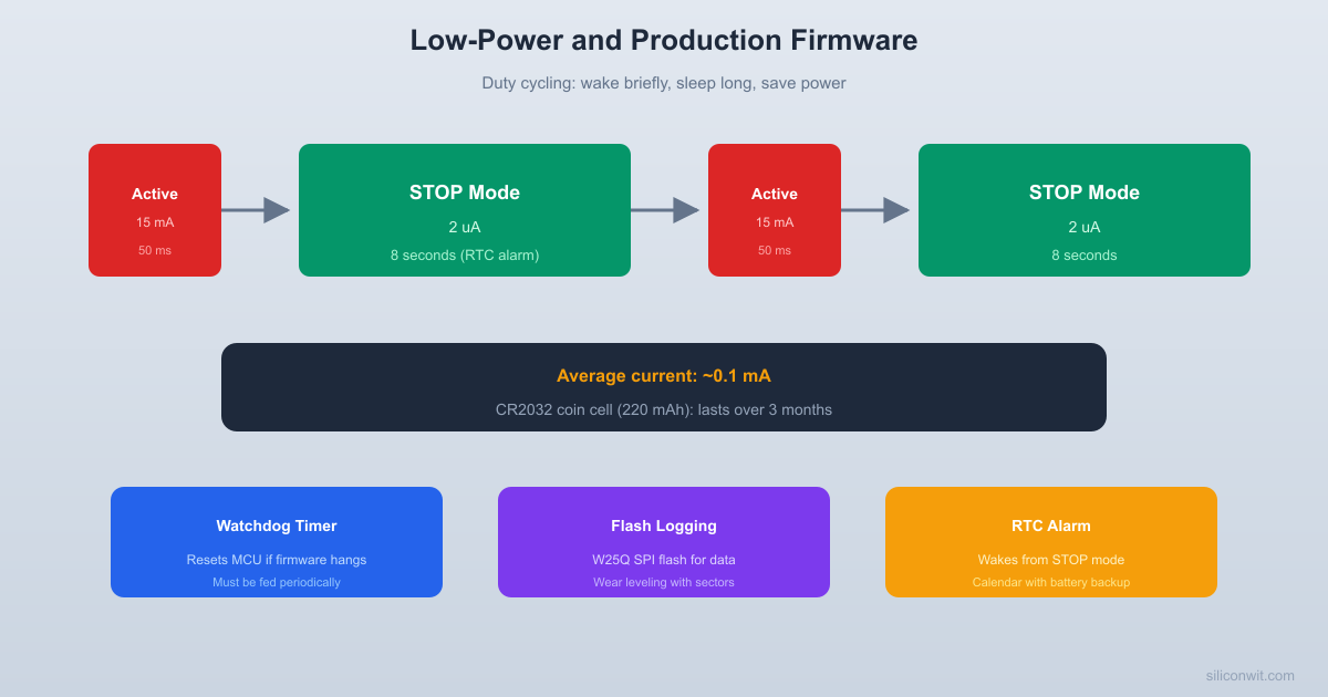
The data logger’s operating cycle consists of brief active periods separated by long Stop mode sleep intervals. This duty-cycling strategy is what makes months of battery life possible.
  Data logger duty cycle:
  Current  15 mA |  *         *         *        |  *         *         *        |  * active  * active  * active        |  * ~50ms   * ~50ms   * ~50ms  1.4uA +--+----+----+----+----+----+-->           |    |    |    |    |    |           sleep    sleep    sleep           60s      60s      60s
  Average current:  (15mA x 0.05s + 1.4uA x 59.95s) / 60s  = ~13.9 uA
  CR2032 (220 mAh) / 13.9 uA = ~1.8 years
The STM32F103 offers three low-power modes with different tradeoffs between power consumption and wakeup time. Choosing the right mode depends on how often you need to wake up and how fast the MCU must respond after waking. For a data logger that wakes every 60 seconds, Stop mode provides the best balance: very low current consumption with all SRAM and register contents preserved.
Mode Comparison
Mode
Current (typical)
Wakeup Time
RAM Preserved
Peripherals
Wakeup Sources
Sleep
~2 mA
Immediate
Yes
All running
Any interrupt
Stop
~1.4 uA
~5 us
Yes
Stopped (RTC runs)
EXTI, RTC alarm
Standby
~1.7 uA
~50 us (reset)
No (lost)
All off (RTC optional)
WKUP pin, RTC, IWDG
Why Stop Mode
SRAM preserved: All variables, peripheral configurations, and the stack survive sleep. After wakeup, execution continues from the WFI instruction. No need to reinitialize everything.
RTC keeps running: The LSE crystal (32.768 kHz) powers the RTC during Stop mode. RTC alarms can wake the MCU at precise intervals.
Fast wakeup: The MCU wakes in microseconds and resumes execution. Compare this to Standby mode, which triggers a full reset.
Low enough: 1.4 uA is sufficient for months of CR2032 operation.
Power Budget Calculation
Sleep current: 1.4 uA (Stop mode)
Active current: ~15 mA for ~50 ms (sensor read + flash write)
Wakeup interval: 60 seconds
Average current = (1.4 uA * 59.95 s + 15 mA * 0.05 s) / 60 s
= (83.93 uAs + 750 uAs) / 60 s
= 833.93 uAs / 60 s
= ~13.9 uA average
CR2032 capacity: 220 mAh = 220,000 uAh
Battery life: 220,000 uAh / 13.9 uA = ~15,827 hours = ~1.8 years
Even with real-world inefficiencies (voltage regulator quiescent current, flash leakage, self-discharge), 6+ months is achievable.
RTC Configuration and Alarm Wakeup
The RTC runs from the 32.768 kHz LSE crystal even during Stop mode. The RTC alarm wakes the CPU by triggering EXTI line 17, which is one of the few interrupt sources active in Stop mode.
  RTC wakeup in Stop mode:
  LSE 32.768 kHz       |  +----+----+  | Prescaler|  /32768 = 1 Hz  +----+----+       |  +----+----+  | RTC CNT  |  increments every second  +----+----+       |     compare  +----+----+  | RTC ALR  |  alarm value  +----+----+       |  match?       v  +----+----+  | EXTI 17  |  wakes CPU from Stop mode  +----+----+       |  +----+----+  | CPU      |  resumes after __WFI()  | wakes up |  (clock reverts to HSI)  +----------+
The RTC on the STM32F103 is a simple 32-bit counter clocked by the LSE oscillator (32.768 kHz). It has a prescaler that divides 32768 Hz down to 1 Hz, incrementing the counter every second. The RTC alarm register triggers an interrupt when the counter matches the alarm value. During Stop mode, the RTC continues running on LSE power, which draws only a few hundred nanoamps.
PWR->CR|= PWR_CR_LPDS; /* Low-power regulator in Stop */
/* Clear wakeup flag */
PWR->CR|= PWR_CR_CWUF;
/* Enter Stop mode (WFI = Wait For Interrupt) */
__WFI();
/* Execution resumes here after RTC alarm wakes us */
/* Reconfigure clock (HSE + PLL, since Stop mode reverts to HSI) */
clock_init();
/* Clear deep sleep bit */
SCB->SCR&=~SCB_SCR_SLEEPDEEP_Msk;
}
W25Q SPI Flash Driver
The W25Q flash stores log entries sequentially. When a sector boundary is reached, the firmware erases the next 4 KB sector before writing. The write pointer wraps around to the beginning when the end of flash is reached.
  W25Q flash log layout (4 MB):
  +--------+--------+--------+-- --+--------+  |Sector 0|Sector 1|Sector 2| ... |Sect.1023  | 4 KB   | 4 KB   | 4 KB   |     | 4 KB   |  +--------+--------+--------+-- --+--------+  |entry 0 |entry341|        |     |        |  |entry 1 |entry342|        |     |        |  |  ...   |  ...   |  <-- write pointer    |  |entry340|        |                       |  +--------+--------+-----------------------+  0x000000  0x001000  0x002000       0x3FFFFF
  Each entry: 12 bytes  Entries per sector: 4096/12 = 341  Total capacity: ~349,000 entries  At 1/min: ~242 days of data
The W25Q32 is a 32 Mbit (4 MB) SPI NOR flash memory. It supports standard SPI at up to 104 MHz clock speed. Flash memory has a write constraint: you can only change bits from 1 to 0 by writing. To change bits from 0 to 1, you must erase an entire sector (4 KB). For data logging, you write sequentially through the flash, erasing sectors ahead of the write pointer when needed. The W25Q also has a power-down mode that reduces standby current from ~1 uA to ~0.1 uA.
Flash Commands
Command
Opcode
Description
Write Enable
0x06
Must precede every write/erase
Page Program
0x02
Write up to 256 bytes
Read Data
0x03
Read any number of bytes
Sector Erase (4KB)
0x20
Erase 4096-byte sector
Read Status Reg 1
0x05
Check busy flag (bit 0)
Power Down
0xB9
Enter low-power mode
Release Power Down
0xAB
Wake from power-down
Read JEDEC ID
0x9F
Manufacturer and device ID
Driver Implementation
#defineW25Q_CS_LOW() GPIOA->BRR= (1<<4)
#defineW25Q_CS_HIGH() GPIOA->BSRR= (1<<4)
voidw25q_write_enable(void) {
W25Q_CS_LOW();
spi1_transfer(0x06);
W25Q_CS_HIGH();
}
voidw25q_wait_busy(void) {
W25Q_CS_LOW();
spi1_transfer(0x05);
while (spi1_transfer(0xFF)&0x01); /* Wait until BUSY clears */
W25Q_CS_HIGH();
}
voidw25q_sector_erase(uint32_taddr) {
w25q_write_enable();
W25Q_CS_LOW();
spi1_transfer(0x20);
spi1_transfer((addr >>16) &0xFF);
spi1_transfer((addr >>8) &0xFF);
spi1_transfer(addr &0xFF);
W25Q_CS_HIGH();
w25q_wait_busy(); /* Sector erase takes 30-400 ms */
The STM32F103 option bytes control read protection, write protection, watchdog configuration, and boot settings. They are stored in a special area of flash at address 0x1FFF_F800. Modifying option bytes requires unlocking the flash, erasing the option byte area, and writing new values. The most important option byte for production is read protection (RDP), which prevents the firmware from being read out through SWD.
/* Enable read protection (Level 1) */
voidenable_read_protection(void) {
/* WARNING: This prevents SWD readout of flash.
* Reverting to Level 0 erases all flash contents. */
FLASH->CR|= FLASH_CR_OPTPG; /* Option byte program */
/* Write RDP key for Level 1 (any value except 0xA5) */
*(volatileuint16_t*)0x1FFFF800=0x00FF;
while (FLASH->SR& FLASH_SR_BSY);
FLASH->CR&=~FLASH_CR_OPTPG;
}
Bootloader Basics
The STM32F103 has a built-in system bootloader in ROM that supports UART firmware updates. By pulling Boot0 high and resetting, the MCU enters bootloader mode and accepts new firmware over USART1. For production, you might want a custom bootloader that lives in the first few KB of flash, verifies firmware integrity (CRC check), and jumps to the application. This lets you update firmware in the field without an ST-Link.
/* Jump to system bootloader from application code */
The Blue Pill board has components that draw current even when the MCU is asleep: the power LED (~2 mA), the 3.3V voltage regulator quiescent current (~5 mA for the AMS1117), and the USB pull-up resistor. For true low-power operation, you need to either desolder the power LED and regulator (powering the MCU directly from the CR2032 at 3V) or use a custom PCB with a low-quiescent-current LDO like the MCP1700 (~1.6 uA).
Component
Current Draw
Action
AMS1117 regulator
~5 mA quiescent
Replace with MCP1700 or power MCU directly
Power LED
~2 mA
Desolder or cut trace
USB pull-up (R10)
~2 mA when USB connected
Disconnect USB for battery operation
STM32 in Stop mode
~1.4 uA
Already optimized
What You Have Learned
Lesson 9 Complete
Low-power design:
STM32 Sleep, Stop, and Standby modes with current consumption and tradeoffs
RTC alarm configuration for periodic wakeup from Stop mode
Power budget calculation for battery life estimation
Peripheral clock and GPIO management for minimum leakage
Flash storage:
W25Q SPI flash commands (read, write, erase, power down)
Sequential write strategy with sector erase for data logging
Write pointer storage in backup registers (survives sleep)
Data retrieval over serial as CSV
Production firmware:
Flash and option byte programming
Read protection (RDP) to prevent firmware extraction
System bootloader access for field firmware updates
Production checklist for reliable deployed firmware
Brown-out detection and battery voltage monitoring
Course summary:
Over nine lessons you have built a complete STM32 skill set: from toolchain setup and bare-register GPIO to FreeRTOS multitasking and battery-powered production firmware. Every peripheral on the Blue Pill has been exercised, debugged, and understood at the register level. These foundations transfer directly to any STM32 family (F4, L4, H7) and to other ARM Cortex-M microcontrollers.
Comments