Most embedded Linux tutorials skip the fundamentals and jump straight into Raspbian. In this lesson, you will do the opposite: set up a cross-compilation toolchain on your host machine, compile a simple C binary for the Raspberry Pi Zero 2 W’s ARM Cortex-A53 processor, and then trace exactly how that binary gets executed during the Linux boot sequence. You will prepare a microSD card with a bootloader, kernel, and minimal root filesystem so that your “hello from custom Linux” message appears on the serial console at first boot. #EmbeddedLinux #CrossCompilation #BootProcess
What We Are Building
Custom First-Boot Binary on RPi Zero 2 W
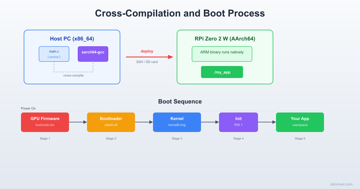
A complete cross-compiled “hello from custom Linux” application that runs automatically when the Raspberry Pi Zero 2 W boots for the first time. The project covers installing the AArch64 cross-toolchain, writing and compiling a C program on your host PC, preparing a bootable microSD card with all four boot stages (firmware blobs, bootloader, kernel, root filesystem), and wiring a USB-serial adapter so you can watch every boot message scroll past in real time.
Project specifications:
Parameter
Value
Target board
Raspberry Pi Zero 2 W (BCM2710A1, Cortex-A53)
Architecture
AArch64 (64-bit ARM)
Cross-toolchain
aarch64-linux-gnu-gcc
Boot stages
GPU firmware, start.elf, U-Boot or config.txt kernel load, init
Root filesystem
Minimal hand-built rootfs (BusyBox)
Serial console
115200 baud via CP2102 or FTDI USB-serial adapter
Storage
microSD card, 16 GB or larger
Host OS
Ubuntu/Debian x86_64 (WSL2 also supported)
Bill of Materials
Ref
Component
Quantity
Notes
1
Raspberry Pi Zero 2 W
1
Quad-core Cortex-A53, Wi-Fi, Bluetooth
2
microSD card (16 GB+)
1
Class 10 or faster recommended
3
USB-serial adapter (CP2102 or FTDI)
1
3.3V logic level required
4
Jumper wires (female-female)
3
TX, RX, GND connections
5
Micro-USB cable
1
Power supply for the Pi
6
5V USB power supply (2.5A)
1
Stable supply prevents boot issues
The Linux Boot Sequence
When you press the power button on a Raspberry Pi Zero 2 W, the board does not jump straight into Linux. Instead, a carefully orchestrated chain of events unfolds, each stage handing control to the next. Understanding this chain is essential because, later in this course, you will modify nearly every link in it.
RPi Zero 2 W Boot Sequence
──────────────────────────────────────────
Power On
│
▼
┌─────────────────┐
│ GPU ROM (SoC) │ Fixed in silicon
│ Loads bootcode │
└────────┬────────┘
▼
┌─────────────────┐
│ start.elf (GPU) │ Reads config.txt
│ Init SDRAM │ Loads kernel + DTB
│ Load kernel │
└────────┬────────┘
▼
┌─────────────────┐
│ Linux Kernel │ ARM cores released
│ Init MMU, CPUs │ Mount rootfs
│ Probe hardware │
└────────┬────────┘
▼
┌─────────────────┐
│ /sbin/init │ PID 1
│ (BusyBox or │ Start services
│ systemd) │ Launch shell
└─────────────────┘
The RPi Zero 2 W uses the Broadcom BCM2710A1 SoC, which contains both a VideoCore IV GPU and a quad-core ARM Cortex-A53 CPU. Critically, it is the GPU that runs first, not the CPU. The ARM cores remain in reset until the GPU firmware explicitly releases them.
GPU ROM bootloader (first stage)
When power is applied, the VideoCore IV GPU starts executing code from a small ROM embedded in the SoC. This ROM is burned into silicon at the factory and cannot be modified. Its only job is to look for the file bootcode.bin on the first FAT32 partition of the SD card. On newer firmware, the ROM loads start.elf directly. If the SD card is missing or the file is not found, the boot stops here and the green LED gives an error blink pattern.
start.elf and config.txt (second stage)
The GPU loads start.elf, which is the main firmware blob. This file initializes SDRAM, reads config.txt to determine hardware configuration (clock speeds, UART, display, GPU memory split), and loads the Linux kernel image into memory. On a 64-bit setup, start.elf reads the kernel parameter from config.txt to find the kernel image file (for example, kernel=Image.gz). It also loads the device tree blob (.dtb file) that describes the hardware layout to the kernel.
Linux kernel boots (third stage)
The GPU releases the ARM cores from reset and passes control to the kernel entry point. The kernel decompresses itself (if using Image.gz), initializes the memory management unit, brings up the CPU cores, and begins probing hardware based on the device tree. You will see kernel log messages on the serial console during this stage. The kernel mounts the root filesystem and looks for the init process.
Init and userspace (fourth stage)
The kernel executes /sbin/init (or whatever the init= kernel command line parameter specifies). In a full Linux distribution this would be systemd, but in our minimal system it will be a BusyBox init that reads /etc/inittab and launches a shell. Your custom “hello from custom Linux” binary runs at this stage.
Why the GPU boots first
The Broadcom SoC was originally designed for multimedia applications where the GPU needed to initialize the display as quickly as possible. This architecture means the ARM CPU is a secondary processor from the hardware’s perspective. The GPU loads firmware, configures clocks and memory, and only then wakes up the ARM cores. This is why the RPi boot process looks different from most ARM boards that use U-Boot or similar ARM-native bootloaders.
Setting Up the Cross-Toolchain
Cross-Compilation: Host vs Target
──────────────────────────────────────────
Host PC (x86_64) Target (AArch64)
───────────────── ────────────────
hello.c RPi Zero 2 W
│ Cortex-A53
▼
aarch64-linux-gnu-gcc Cannot run x86
│ binaries!
▼
hello (AArch64 ELF) ─────► Runs here ✓
│
✗ Cannot run
on host
Cross-compilation means compiling code on one machine (the host) to produce executables for a different machine (the target). Your host is an x86_64 PC running Ubuntu or Debian. Your target is the Raspberry Pi Zero 2 W running an AArch64 (64-bit ARM) processor. You cannot run x86 binaries on ARM or vice versa, so you need a special compiler that runs on x86 but produces ARM machine code.
The cross-toolchain includes a compiler (aarch64-linux-gnu-gcc), a linker, an assembler, and supporting libraries. The prefix aarch64-linux-gnu- tells you exactly what it targets: the AArch64 architecture, Linux operating system, GNU C library.
Confirm it produces AArch64 binaries by checking the target:
Terminal window
aarch64-linux-gnu-gcc-dumpmachine
Expected output:
aarch64-linux-gnu
You will also need a few other packages for working with SD cards, serial consoles, and filesystem images:
Terminal window
sudoaptinstall-yminicompicocomdosfstoolsparted\
debootstrapqemu-user-staticbinfmt-support
Why not compile natively on the Pi?
The Raspberry Pi Zero 2 W has only 512 MB of RAM and a relatively slow CPU. Compiling a C program natively takes much longer than cross-compiling on a modern PC. When you build the Linux kernel later in this course, the difference is dramatic: what takes 5 minutes on your host could take over an hour on the Pi. Cross-compilation is standard practice in embedded Linux development.
Wiring the Serial Console
The serial console is your primary debugging interface. Unlike SSH (which requires a working network stack), the serial console works from the very first moments of boot. You will see GPU firmware messages, kernel logs, and your shell prompt, all through three wires.
The Raspberry Pi Zero 2 W exposes a UART on its GPIO header:
RPi GPIO Pin
Function
Connects To (USB-Serial Adapter)
GPIO14 (Pin 8)
TXD (Transmit)
RXD on adapter
GPIO15 (Pin 10)
RXD (Receive)
TXD on adapter
GND (Pin 6)
Ground
GND on adapter
Important wiring notes
TX connects to RX and RX connects to TX. This is the most common mistake. The Pi’s transmit pin sends data to the adapter’s receive pin, and vice versa. Also, the Raspberry Pi GPIO operates at 3.3V logic levels. Never connect a 5V serial adapter directly to the GPIO pins or you will damage the SoC. The CP2102 and most FTDI adapters have a 3.3V mode. Check your adapter before connecting. Do not connect the VCC/5V pin from the adapter to the Pi unless you intend to power the Pi through GPIO (which is not recommended for beginners).
After wiring, plug the USB-serial adapter into your host PC. It will appear as a device file, typically /dev/ttyUSB0 or /dev/ttyACM0. Check which device appeared:
Terminal window
ls/dev/ttyUSB*
Open a serial terminal using minicom:
Terminal window
sudominicom-b115200-D/dev/ttyUSB0
Or using picocom (simpler interface, recommended):
Terminal window
sudopicocom-b115200/dev/ttyUSB0
If you get a “permission denied” error, add your user to the dialout group:
Terminal window
sudousermod-aGdialout$USER
Log out and log back in for the group change to take effect. After that you can run picocom without sudo.
The baud rate 115200 is the default serial speed configured in the Raspberry Pi firmware. Both the Pi and your terminal program must use the same baud rate or you will see garbled characters. The full serial parameters are 115200 baud, 8 data bits, no parity, 1 stop bit (often written as 115200 8N1).
Cross-Compiling Your First Binary
Now that the toolchain is installed, write a small C program that reads system information from the Linux virtual filesystem. This program will later run on the Pi to confirm that your entire toolchain and boot setup works correctly.
The -static flag links all libraries into the binary so it does not depend on shared libraries on the target. This is important because our minimal root filesystem will not have a full set of shared libraries yet.
Verify the binary is an AArch64 ELF executable:
Terminal window
filehello_linux
Expected output:
hello_linux: ELF 64-bit LSB executable, ARM aarch64, version 1 (GNU/Linux),
statically linked, BuildID[sha1]=..., for GNU/Linux 3.7.0, not stripped
The key details: 64-bit, ARM aarch64, and statically linked. If you see x86-64 instead, you accidentally used the system’s native gcc rather than the cross-compiler.
You can also check the binary size:
Terminal window
ls-lhhello_linux
A statically linked binary will be larger (around 700 KB to 1 MB) because it includes the C library. For production embedded systems you would use a smaller C library like musl, but for this lesson glibc is fine.
Building a Minimal Root Filesystem
A root filesystem (rootfs) is the directory tree that Linux mounts as / at boot. In a desktop distribution, this contains tens of thousands of files. For an embedded system, you need far less. The minimum is: an init program, a few device nodes, and the virtual filesystems /proc and /sys mounted at boot.
BusyBox is a single binary that provides hundreds of common Unix utilities (sh, ls, cat, mount, ifconfig, and many more). By installing BusyBox as your shell and init, you get a functional Linux userspace in a single file.
You can either cross-compile BusyBox from source (covered in a later lesson) or download a prebuilt static binary. For this lesson, build a quick static BusyBox:
This file tells BusyBox init what to do at startup:
Terminal window
cat>~/rpi-embedded/rootfs/etc/inittab<<'INITTAB'
::sysinit:/etc/init.d/rcS
::respawn:/sbin/getty -L console 115200 vt100
::shutdown:/bin/umount -a -r
INITTAB
The three lines mean: run the startup script once, then spawn a login shell on the console (respawning if it exits), and unmount all filesystems on shutdown.
Create the startup script
mkdir-p~/rpi-embedded/rootfs/etc/init.d
cat>~/rpi-embedded/rootfs/etc/init.d/rcS<<'RCS'
#!/bin/sh
echo "Mounting virtual filesystems..."
mount -t proc none /proc
mount -t sysfs none /sys
mount -t devtmpfs none /dev
echo ""
/bin/hello_linux
echo ""
echo "System ready."
RCS
chmod+x~/rpi-embedded/rootfs/etc/init.d/rcS
This script mounts the essential virtual filesystems that programs need (for example, /proc/cpuinfo only exists after /proc is mounted), then runs your hello binary.
Create a basic passwd file
Terminal window
cat>~/rpi-embedded/rootfs/etc/passwd<<'PASSWD'
root::0:0:root:/root:/bin/sh
PASSWD
cat>~/rpi-embedded/rootfs/etc/group<<'GROUP'
root:x:0:
GROUP
mkdir-p~/rpi-embedded/rootfs/root
This creates a root user with no password, which is fine for embedded development. You will add proper authentication in a later lesson.
Your rootfs directory should now look like this:
Directoryrootfs/
Directorybin/
busybox
hello_linux
sh
ls
mount
Directorydev/
…
Directoryetc/
inittab
passwd
group
Directoryinit.d/
rcS
Directorylib/
…
Directoryproc/
…
Directoryroot/
…
Directorysbin/
init
getty
Directorysys/
…
Directorytmp/
…
Directoryusr/
Directorybin/
…
Directorysbin/
…
Directoryvar/
Directorylog/
…
Note that bin/sh, sbin/init, sbin/getty, and many other files are symlinks to bin/busybox.
Preparing the SD Card
The microSD card needs two partitions: a small FAT32 boot partition containing the GPU firmware, device tree, kernel, and config.txt, and a larger ext4 root partition containing your rootfs.
Warning: this will erase the SD card
The following commands will destroy all data on the SD card. Double-check the device name before running them. If your SD card is /dev/sdb, make absolutely sure it is not your system drive. You can verify by checking the size with lsblk.
Insert the SD card and identify its device name:
Terminal window
lsblk
Look for the newly appeared device (typically /dev/sdb or /dev/mmcblk0). In the commands below, replace /dev/sdX with your actual device.
Everything must be on a single line. The parameters tell the kernel to use the serial port for console output, mount the second SD card partition as the root filesystem, and use /sbin/init as the first userspace process.
Copy rootfs to the root partition
Terminal window
sudocp-a~/rpi-embedded/rootfs/*/mnt/rootfs/
The -a flag preserves permissions, ownership, and symlinks.
Unmount and sync
Terminal window
sudoumount/mnt/boot
sudoumount/mnt/rootfs
sync
First Boot
With the SD card prepared, it is time to see everything come together.
Insert the microSD card into the Raspberry Pi Zero 2 W.
Connect the USB-serial adapter wires (TX, RX, GND) as described in the wiring section.
Open your serial terminal on the host: picocom -b 115200 /dev/ttyUSB0
Plug in the micro-USB power cable to the Pi.
You should see boot messages scrolling in your terminal. The output will look something like this:
[ 0.000000] Booting Linux on physical CPU 0x0000000000 [0x410fd034]
[ 0.000000] Linux version 6.6.x-v8+ (gcc version 12.3.0) #1 SMP PREEMPT ...
[ 0.000000] Machine model: Raspberry Pi Zero 2 W Rev 1.0
[ 0.000000] Memory: 440560K/524288K available ...
...
[ 1.234567] mmc0: new high speed SDHC card at address 0001
[ 1.240000] mmcblk0: mmc0:0001 SD 14.8 GiB
[ 1.245000] mmcblk0: p1 p2
...
[ 2.100000] EXT4-fs (mmcblk0p2): mounted filesystem with ordered data mode.
After the startup script runs, BusyBox getty spawns a login shell. Press Enter and you should see a # prompt (root shell with no password). You can now run commands directly on the Pi through the serial console.
Troubleshooting
No output at all: Check your TX/RX wiring (swap them if needed). Verify the adapter is 3.3V. Confirm the baud rate is 115200.
Garbled characters: Baud rate mismatch. Make sure both sides use 115200.
Kernel panic, no init found: The root filesystem path in cmdline.txt is wrong, or /sbin/init does not exist in the rootfs. Verify your cmdline.txt says root=/dev/mmcblk0p2 and that you copied the rootfs correctly.
Kernel boots but no “Hello” message: The init script /etc/init.d/rcS might not be executable. Re-mount the SD card on your host and run chmod +x on it.
How config.txt Works
The config.txt file is not a Linux configuration file. It is read by the GPU firmware (start.elf) before the ARM CPU even starts. Think of it as the BIOS settings for the Raspberry Pi. Here are the key parameters you should understand:
Parameter
Value
Purpose
arm_64bit=1
1
Boot in 64-bit (AArch64) mode. Without this, the Pi boots in 32-bit mode even though the Cortex-A53 supports 64-bit.
kernel=kernel8.img
filename
Specifies which kernel image file to load from the boot partition.
enable_uart=1
1
Enables the primary UART (serial port) on GPIO14/15. This is essential for serial console access.
dtoverlay=miniuart-bt
overlay name
Moves Bluetooth to the mini UART and gives the full PL011 UART to the serial console. The PL011 is more reliable because it has a proper clock source.
gpu_mem=16
MB
Allocates only 16 MB of RAM to the GPU, leaving the rest for the ARM cores. Since we are running a headless embedded system, the GPU needs minimal memory.
disable_splash=1
1
Skips the rainbow splash screen, saving a fraction of a second during boot.
boot_delay=0
seconds
Eliminates the default 1-second delay before loading the kernel.
You can also set CPU and RAM clock speeds, enable or disable specific hardware interfaces, and load device tree overlays for add-on boards. The full list of parameters is documented at rpf.io/configtxt.
Some additional useful parameters for embedded work:
# Set fixed core frequency (avoids clock scaling during timing-sensitive work)
force_turbo=1
arm_freq=1000
# Disable HDMI to save power (about 25 mA)
hdmi_blanking=2
# Disable camera and display interfaces
start_x=0
config.txt vs cmdline.txt
These two files serve different purposes and are read at different times. config.txt is read by the GPU firmware to configure hardware before Linux starts. cmdline.txt is passed to the Linux kernel as its command line arguments. Hardware settings go in config.txt; kernel behavior settings go in cmdline.txt.
Exercises
Exercise 1: Extend the hello binary
Modify hello_linux.c to also read and display /proc/device-tree/model (which contains the board name string). Cross-compile it, copy it to the SD card, and verify the output on boot. Hint: the file contains a plain string, not key-value pairs.
Exercise 2: Add a second program
Write a second C program called countdown.c that prints a countdown from 10 to 1 (one number per second, using the sleep() function) and then prints “Liftoff!”. Cross-compile it, add it to the rootfs, and modify /etc/init.d/rcS to run it after hello_linux. Observe the output on the serial console.
Exercise 3: Explore the boot partition
After booting into your minimal Linux, mount the boot partition from the running Pi: mount /dev/mmcblk0p1 /tmp. Then use ls and cat to examine config.txt and cmdline.txt from within the Pi. Compare what you see with the files you created on your host machine.
Exercise 4: Measure boot time
Add printk.time=1 to cmdline.txt (on the same line, separated by a space). Reboot and look at the timestamps in the kernel log. Record the timestamp of the last kernel message before “Mounting virtual filesystems” appears. This is roughly your kernel boot time. Write down this number; you will compare it against the optimized kernel in Lesson 2.
Comments