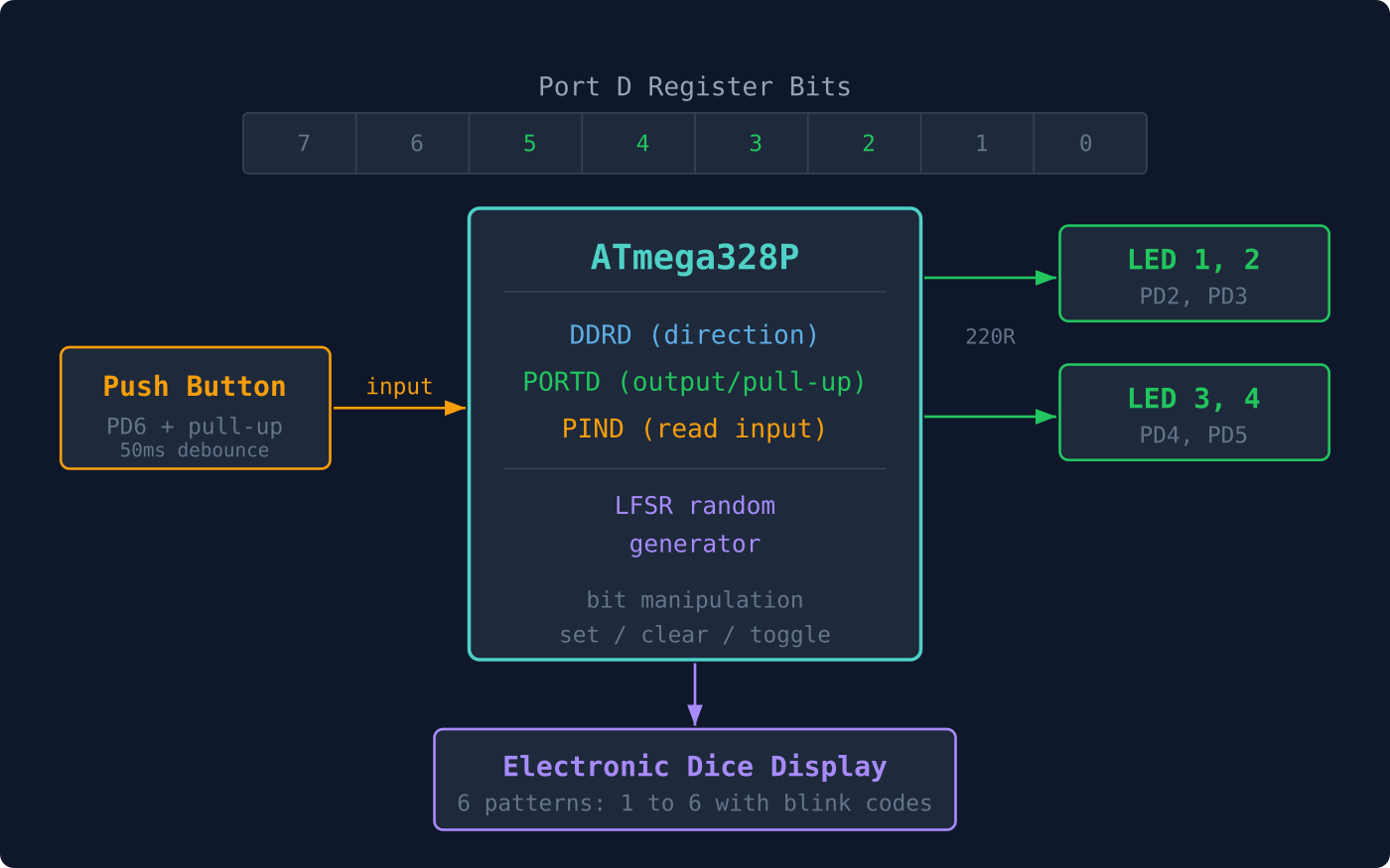
Every pin on the ATmega328P is controlled by three registers: DDRx sets direction, PORTx drives output or enables pull-ups, and PINx reads the physical voltage level. Understanding these registers is the foundation for all digital interfacing. In this lesson you will wire up four LEDs and a push button, then write firmware for an electronic dice that rolls a random number on each button press. No digitalRead(), no digitalWrite(), just clean bit manipulation on bare hardware. #GPIO #BitManipulation #AVR
What We Are Building
Electronic Dice
Press a button and four LEDs light up in a pattern representing a dice face (1 through 6). The random number comes from a 16-bit linear feedback shift register (LFSR) that runs continuously in the main loop. Button debouncing is handled in software with a simple delay-based check. The LED patterns map dice pips to specific pin combinations.
Project specifications:
Parameter
Value
MCU
ATmega328P (on Arduino Nano or Uno)
LEDs
4 (on PD2, PD3, PD4, PD5)
Button
1 (on PD6, active low with pull-up)
PRNG
16-bit Galois LFSR
Debounce
50 ms delay-based
Current per LED
~10 mA (220 ohm resistor)
Dice range
1 to 6
Parts for This Lesson
Ref
Component
Quantity
Notes
1
Arduino Nano or Uno (ATmega328P)
1
From Lesson 1
2
Breadboard
1
From Lesson 1
3
LED (any color, 3mm/5mm)
4
3 new plus 1 from Lesson 1
4
220 ohm resistor
4
3 new plus 1 from Lesson 1
5
Push button (tactile switch)
1
6mm through-hole
6
10K ohm resistor
1
External pull-up (or use internal)
7
Jumper wires
~10
Male-to-male
GPIO Register Overview
The ATmega328P groups its 23 I/O pins into three ports: Port B (PB0 through PB7), Port C (PC0 through PC6), and Port D (PD0 through PD7). Each port has three registers. DDRx (Data Direction Register) sets each pin as input (0) or output (1). PORTx (Port Data Register) drives high/low on outputs or enables the internal pull-up on inputs. PINx (Port Input Pins Register) reads the current logic level regardless of direction.
Register
Read/Write
Purpose
DDRx
R/W
Set pin direction: 1 = output, 0 = input
PORTx
R/W
Output: drive high/low. Input: enable pull-up
PINx
R
Read pin logic level
For a single pin, the DDRx and PORTx bits combine to select one of four configurations:
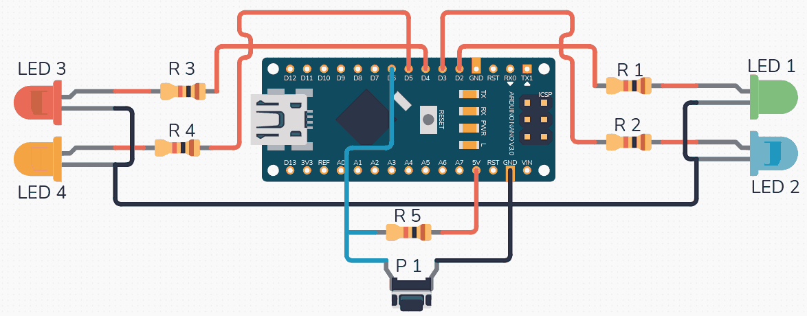
Wire the four LEDs with their anodes to PD2 through PD5 (through 220 ohm resistors to ground). Connect the push button between PD6 and ground, with a 10K pull-up resistor to VCC.
ATmega328P
+-----------+
| |
| PD6-+---+---[10K]---VCC
| | |
| | [BTN] (press = LOW)
| | |
| | GND
| |
| PD2--+--[220R]--[LED1]--GND
| PD3--+--[220R]--[LED2]--GND
| PD4--+--[220R]--[LED3]--GND
| PD5--+--[220R]--[LED4]--GND
| |
+-----+-----+
|
GND
Alternatively, you can skip the external pull-up and enable the internal pull-up in software by setting the PORTx bit while the pin is configured as input.
Signal
Arduino Nano Pin
ATmega328P Pin
Connection
LED 1
D2
PD2
LED anode, 220R to GND
LED 2
D3
PD3
LED anode, 220R to GND
LED 3
D4
PD4
LED anode, 220R to GND
LED 4
D5
PD5
LED anode, 220R to GND
Button
D6
PD6
Button to GND, 10K to VCC
The LFSR Random Number Generator
A linear feedback shift register produces pseudo-random numbers using only XOR and shift operations. It needs no multiplication or division, making it ideal for small microcontrollers. The Galois form is particularly efficient: each step shifts the register right by one, and if the outgoing bit is 1, the register is XORed with a polynomial tap mask. For a 16-bit LFSR with taps at bits 16, 14, 13, and 11, the sequence repeats after 65535 values.
staticuint16_t lfsr =0xACE1; /* Non-zero seed */
staticuint8_troll_dice(void)
{
/* Galois LFSR step */
uint8_t lsb = lfsr &1;
lfsr >>=1;
if (lsb) lfsr ^=0xB400; /* Taps at 16,14,13,11 */
return (lfsr %6) +1; /* Result: 1 to 6 */
}
Dice LED Patterns
A real dice has a specific pip layout for each face. With four LEDs arranged in a square, you can represent all six faces by choosing which LEDs to light. The mapping below uses LED1 (top-left), LED2 (top-right), LED3 (bottom-left), and LED4 (bottom-right).
Dice Value
LED1
LED2
LED3
LED4
Pattern
1
OFF
ON
OFF
OFF
Center-ish
2
ON
OFF
OFF
ON
Diagonal
3
ON
OFF
ON
ON
Triangle
4
ON
ON
ON
ON
All corners
5
ON
ON
ON
ON
All + single blink
6
ON
ON
ON
ON
All + double blink
Complete Firmware
#defineF_CPU16000000UL
#include<avr/io.h>
#include<util/delay.h>
/* Variable-length delay: _delay_ms() requires a compile-time
constant on many avr-gcc versions, so we wrap it in a loop. */
case5: /* All + single blink to distinguish from 4 */
pattern = (1<<PD2)|(1<<PD3)|(1<<PD4)|(1<<PD5);
PORTD |= pattern;
delay_ms(100);
PORTD &=~LED_MASK;
delay_ms(100);
break;
case6: /* All + double blink to distinguish from 4 and 5 */
pattern = (1<<PD2)|(1<<PD3)|(1<<PD4)|(1<<PD5);
PORTD |= pattern;
delay_ms(100);
PORTD &=~LED_MASK;
delay_ms(100);
PORTD |= pattern;
delay_ms(100);
PORTD &=~LED_MASK;
delay_ms(100);
break;
}
PORTD |= pattern;
}
staticuint8_tbutton_pressed(void)
{
if (!(PIND & (1<< BTN_PIN))) {
_delay_ms(50); /* Debounce */
if (!(PIND & (1<< BTN_PIN))) {
return1;
}
}
return0;
}
intmain(void)
{
/* LEDs as outputs */
DDRD |= LED_MASK;
/* Button as input with internal pull-up */
DDRD &=~(1<< BTN_PIN);
PORTD |= (1<< BTN_PIN);
uint8_t last_value =1;
show_dice(last_value);
while (1) {
/* Keep the LFSR running for randomness */
(void)roll_dice();
if (button_pressed()) {
/* Rolling animation */
for (uint8_t i =0; i <10; i++) {
show_dice((i %6) +1);
delay_ms(50+ i *20);
}
last_value =roll_dice();
show_dice(last_value);
/* Wait for button release */
while (!(PIND & (1<< BTN_PIN)));
_delay_ms(50);
}
}
}
Compiling and Flashing
Use the same Makefile structure from Lesson 1. Update main.c with the dice code, then:
Terminal window
makeflash
Press the button and watch the LEDs cycle through a rolling animation before settling on a random dice value.
Understanding Pull-Up Resistors
The following diagram compares a floating input (unpredictable readings) with a pulled-up input (stable HIGH until grounded by a switch):
  Floating input:          Pull-up input:
     ???                       VCC      |                         |      | (noise couples in)     [R] 10K (ext) or      |                         |  20-50K (int)   +--+--+                  +--+--+   | PINx | reads random    | PINx | reads HIGH   +--+--+                  +--+--+      |                         |     (nothing)              [Switch]--GND                            (press = LOW)
When a pin is configured as input, it is high-impedance and will float to unpredictable values if left unconnected. A pull-up resistor ties the pin to VCC so it reads high by default. Pressing the button connects the pin to ground, pulling it low. The ATmega328P has built-in pull-up resistors (20K to 50K typical) that you enable by writing a 1 to the PORTx bit while DDRx is 0. External 10K pull-ups give a stronger, more predictable pull-up current.
Exercises
Modify the dice to support values 1 through 8 by adding unique blink patterns for 7 and 8 (for example, alternating flashes).
Replace the delay-based debounce with a state machine that samples the button every 5 ms and requires three consecutive identical readings before accepting a press.
Add a “cheat mode”: if you hold the button for more than 2 seconds, always roll a 6.
Measure the current drawn by each LED with a multimeter. Verify it matches the calculation: (5V minus LED forward voltage) divided by 220 ohms.
Summary
You now understand the three GPIO registers (DDRx, PORTx, PINx) and how to use bit manipulation to control individual pins. You have implemented software debouncing, used a Galois LFSR for pseudo-random numbers, and driven multiple LEDs with distinct patterns. These register-level techniques apply to every peripheral on the ATmega328P, not just GPIO.
Comments