Skip to content

Stepper Motors and Encoder Feedback

Stepper Motors and Encoder Feedback hero image
Modified:
Published:

Stepper motors move in precise, repeatable increments without needing a feedback sensor for basic operation. Pair one with a proper acceleration profile and you get smooth, accurate positioning at speeds that would cause a constant-velocity approach to stall. Add a rotary encoder for user input and limit switches for homing, and you have the core motion control system found in CNC machines, 3D printers, and laboratory equipment. In this lesson you will build a complete linear positioning stage on the Blue Pill using the A4988 stepper driver, hardware timer step generation, trapezoidal acceleration, and STM32 encoder mode. #STM32 #StepperMotor #MotionControl

What We Are Building

Precision Linear Positioning Stage

A positioning system that homes automatically on startup, lets you dial in a target position with a rotary encoder, and moves the stepper motor to that position using a trapezoidal acceleration profile. Limit switches prevent overtravel, UART output provides real-time position feedback, and an LED indicates the system state (homing, idle, moving, limit hit).

Project specifications:

ParameterValue
BoardBlue Pill (STM32F103C8T6)
MotorNEMA 17 bipolar stepper, 200 steps/rev, 1.8 degrees/step
DriverA4988 with adjustable microstepping
Microstepping1/8 step (1600 steps/rev)
EncoderRotary encoder with quadrature A/B channels and push button
Limit switches2x normally closed (NC) microswitches
Power12V 1A+ for motor, 3.3V from Blue Pill for logic
Step timerTIM2 output compare interrupt
Encoder timerTIM3 encoder mode
Max speed800 steps/sec (at 1/8 microstepping)
Acceleration2000 steps/sec^2

Stepper Motor Fundamentals


A bipolar stepper motor has two coils (phases) and four wires. By energizing the coils in sequence, the rotor advances one step at a time. A standard NEMA 17 with 200 steps per revolution gives 1.8 degrees per step.

Stepping modes:

ModeSteps/RevResolutionTorqueSmoothness
Full step2001.8 deg100% ratedRough, noisy
Half step4000.9 deg~70% ratedModerate
1/4 step8000.45 deg~50% ratedSmooth
1/8 step16000.225 deg~40% ratedVery smooth
1/16 step32000.1125 deg~30% ratedSmoothest

Key terms:

  • Holding torque: torque the motor exerts when energized but stationary (typically 0.2 to 0.5 Nm for NEMA 17)
  • Detent torque: small torque felt when turning a de-energized stepper (from the permanent magnets)
  • Pull-out torque curve: torque decreases as speed increases, eventually the motor stalls

We use 1/8 microstepping as a good balance between resolution, torque, and smoothness. The A4988 handles all the current sequencing internally.

A4988 Driver Module


The A4988 takes two control signals from the MCU (STEP and DIR) and drives the motor coils with the correct current waveforms. It handles microstepping, current limiting, and coil sequencing.

A4988 Stepper Driver Wiring
12V Supply
┌────────────────┴────────────────┐
│ A4988 Module │
│ │
│ VMOT ─── 12V VDD ─── 3.3V │
│ GND ──── GND GND ─── GND │
│ │
│ STEP <── PA0 DIR <── PA1 │
│ (TIM2) (GPIO) │
│ │
│ ENABLE <── PA2 (active low) │
│ MS1 <── PB3 │
│ MS2 <── PB4 (1/8 step: │
│ MS3 <── PB5 H, H, L) │
│ │
│ 1A ──┐ ┌── 2A │
│ 1B ──┤ NEMA 17 ├── 2B │
│ └─────────┘ │
└──────────────────────────────────┘

Pin functions:

A4988 PinFunctionConnection
VMOTMotor power (8V to 35V)12V supply positive
GND (motor side)Motor power ground12V supply ground and Blue Pill GND
1A, 1BMotor coil 1NEMA 17 coil 1 wires
2A, 2BMotor coil 2NEMA 17 coil 2 wires
VDDLogic power (3.3V to 5V)Blue Pill 3.3V
GND (logic side)Logic groundBlue Pill GND
STEPStep pulse input (rising edge = one step)PA0 (TIM2_CH1)
DIRDirection (HIGH = CW, LOW = CCW)PA1
ENABLEActive low enable (LOW = motor energized)PA2
MS1Microstepping select bit 0PB3
MS2Microstepping select bit 1PB4
MS3Microstepping select bit 2PB5
SLEEPActive low sleep (tie to RESET if unused)Tied to RESET
RESETActive low reset (tie to SLEEP if unused)Tied to SLEEP

Microstepping selection (active-high logic with internal pull-downs):

MS1MS2MS3Resolution
LOWLOWLOWFull step
HIGHLOWLOWHalf step
LOWHIGHLOW1/4 step
HIGHHIGHLOW1/8 step
HIGHHIGHHIGH1/16 step

Current limiting. The A4988 has a trimmer potentiometer that sets the maximum coil current. The relationship is: Vref = Imax x 8 x Rsense. With typical 0.1 ohm sense resistors, Vref = Imax x 0.8. For a motor rated at 1.2A, set Vref to about 0.96V. Measure Vref between the trimmer wiper and GND with a multimeter while adjusting.

Wiring


A4988 to Blue Pill

A4988 PinBlue Pill PinNotes
STEPPA0Timer output for step pulses
DIRPA1GPIO output, direction control
ENABLEPA2GPIO output, active low
MS1PB3GPIO output, set HIGH for 1/8 step
MS2PB4GPIO output, set HIGH for 1/8 step
MS3PB5GPIO output, set LOW for 1/8 step
VDD3.3VLogic power
GNDGNDCommon ground

Rotary Encoder to Blue Pill (TIM3 Encoder Mode)

Encoder PinBlue Pill PinNotes
A (CLK)PA6 (TIM3_CH1)Quadrature channel A
B (DT)PA7 (TIM3_CH2)Quadrature channel B
SW (push button)PB10GPIO input with pull-up
+3.3VPower
GNDGNDGround

Limit Switches

SwitchBlue Pill PinWiring
Home limit (min)PB14NC switch: one terminal to PB14, other to GND. Enable internal pull-up.
End limit (max)PB15NC switch: one terminal to PB15, other to GND. Enable internal pull-up.

Other Connections

ComponentBlue Pill PinNotes
Status LED (anode)PC13Onboard LED (active low on Blue Pill)
UART TXPA9 (USART1_TX)Debug output at 115200 baud
UART RXPA10 (USART1_RX)Optional command input

Power

ConnectionNotes
12V supply (+) to A4988 VMOTMotor power
12V supply (-) to A4988 GND (motor side) and Blue Pill GNDCommon ground is essential
Blue Pill powered via ST-Link USB or separate 3.3VDo not power the Blue Pill from 12V directly

CubeMX Configuration


  1. Create a new STM32CubeIDE project for STM32F103C8Tx.

  2. TIM2 for step pulse generation. In Timers, enable TIM2. Set Channel 1 to “Output Compare No Output” (we use the interrupt, not the physical pin output). Set Prescaler to 71 (72 MHz / 72 = 1 MHz tick). ARR (period) will be set dynamically in code. Enable TIM2 global interrupt in NVIC.

  3. TIM3 for encoder. In Timers, enable TIM3 with Combined Channels set to “Encoder Mode”. Both Channel 1 (PA6) and Channel 2 (PA7) will be configured automatically. Set encoder mode to “Encoder Mode TI1 and TI2” for 4x counting. Set the counter period (ARR) to 65535. Set the filter to 0x0F for debouncing.

  4. USART1 for debug output. In Connectivity, enable USART1 in Asynchronous mode. Baud rate 115200, 8N1.

  5. GPIO outputs. PA1 (DIR), PA2 (ENABLE), PB3 (MS1), PB4 (MS2), PB5 (MS3), all as GPIO_Output.

  6. GPIO inputs. PB10 (encoder button) as GPIO_Input with pull-up. PB14 and PB15 (limit switches) as GPIO_Input with pull-up.

  7. Clock configuration. HSE 8 MHz, PLL to 72 MHz. APB1 = 36 MHz (TIM2 and TIM3 timers get 72 MHz after the x2 multiplier). APB2 = 72 MHz.

  8. Generate code and open the project.

Step Generation with Timer


The key insight for smooth stepper control: instead of using HAL_Delay() between steps (which blocks the CPU and prevents any other processing), we use a timer interrupt. Each time the timer fires, we toggle the STEP pin and advance the step counter. By changing the timer period between interrupts, we control the step rate, which directly controls speed.

Calculating timer period for a desired step rate:

With a 1 MHz timer tick (prescaler = 71), the timer period in ticks equals 1,000,000 divided by the desired step rate in steps per second. For example, 400 steps/sec needs a period of 2500 ticks.

Desired SpeedSteps/sec (at 1/8 step)Timer Period (ticks)RPM
Slow20050007.5
Medium400250015
Fast800125030
Maximum160062560

Acceleration Profiles


Starting a stepper motor at high speed causes missed steps because the rotor cannot accelerate instantly. The solution is a trapezoidal velocity profile: ramp up from zero to cruise speed, hold cruise speed, then ramp down to zero at the target position.

Trapezoidal Velocity Profile
Speed
(steps/s)
800 │ ┌──────────────┐
│ /│ Cruise │\
│ / │ │ \
│ / │ │ \
│ / │ │ \
│ / │ │ \
0 │───/─────┴──────────────┴─────\──
└─────────────────────────────────>
Accel Cruise Decel
Phase Phase Phase
Position (steps)

Trapezoidal profile phases:

PhaseDescriptionTimer Period
AccelerateSpeed increases linearly from start speed to cruise speedPeriod decreases each step
CruiseConstant speed at maximum velocityPeriod stays constant
DecelerateSpeed decreases linearly from cruise speed to stopPeriod increases each step

The acceleration is implemented by adjusting the timer period after each step. For linear acceleration, the period change per step follows: new_period = old_period - (old_period^2 * acceleration) / timer_freq^2. A simplified integer approximation works well in practice.

Rotary Encoder with Timer Encoder Mode


The STM32’s timer encoder mode is a hardware feature that counts quadrature encoder pulses without any software intervention. The timer counter register automatically increments or decrements based on the A and B channel phase relationship, giving you direction detection for free.

In “Encoder Mode TI1 and TI2” (4x counting), every edge of both channels triggers a count, giving four counts per encoder detent. A typical encoder with 20 detents per revolution produces 80 counts per revolution.

The encoder counter is 16-bit (0 to 65535). We set the counter midpoint (32768) as the initial position so the encoder can turn in both directions without wrapping immediately.

Limit Switches and Homing


Limit switches are wired as normally closed (NC) to ground. When the switch is not pressed, the circuit is closed and the pin reads LOW (through the pull-up and the closed switch to GND, the current path keeps the pin LOW). Wait, let us clarify: with a pull-up resistor enabled and the NC switch connected between the pin and GND, when the switch is closed (not triggered), the pin reads LOW. When the carriage hits the switch and opens it, the pin reads HIGH (pulled up). This is fail-safe: a broken wire reads the same as a triggered switch, stopping motion.

Homing sequence:

  1. Move toward the home limit switch at slow speed (1/4 of cruise speed).

  2. When the home limit switch triggers (pin goes HIGH), stop immediately.

  3. Back off slowly (move in the opposite direction) until the switch closes again (pin goes LOW).

  4. Move forward very slowly (1/8 of cruise speed) until the switch triggers once more. This second trigger gives a precise, repeatable home position.

  5. Set the step counter to zero. This is now the origin.

  6. Apply software limits based on the known travel range.

Complete Project Code


main.c
/* Includes */
#include "main.h"
#include <string.h>
#include <stdio.h>
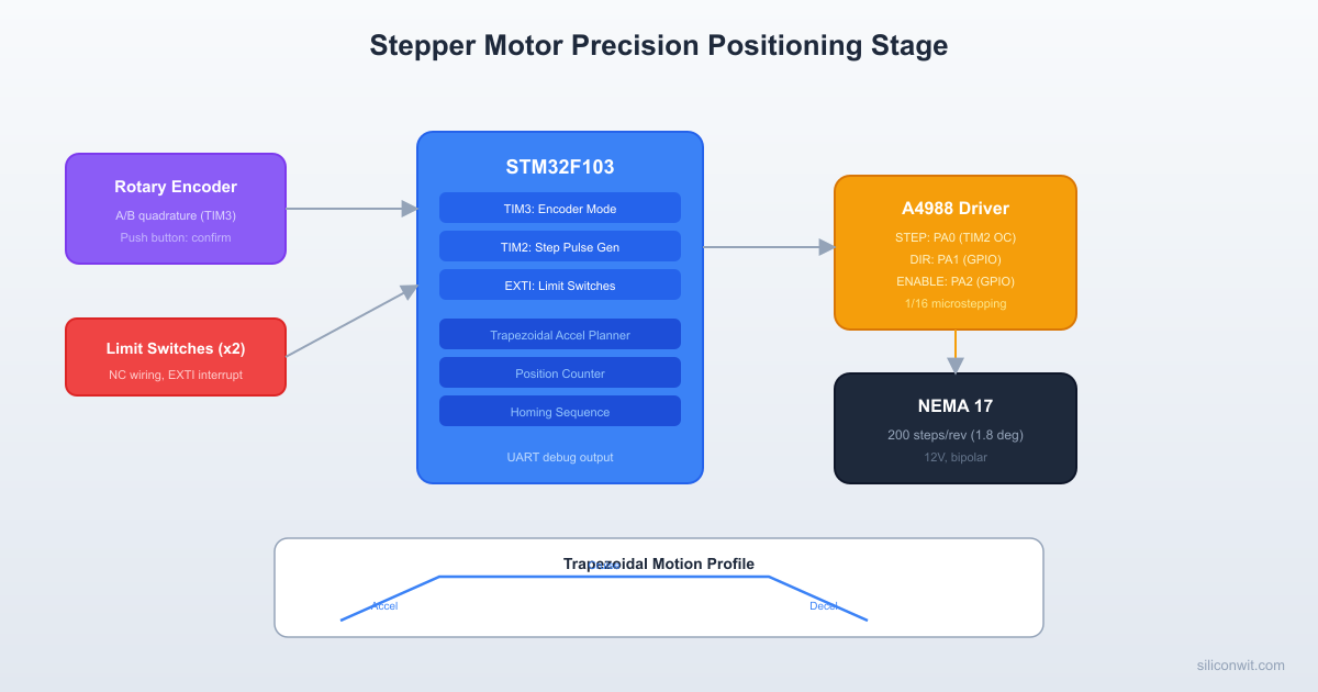
/* --- Peripheral handles --- */
static TIM_HandleTypeDef htim2; /* Step pulse timer */
static TIM_HandleTypeDef htim3; /* Encoder timer */
static UART_HandleTypeDef huart1;
/* --- Stepper configuration --- */
#define STEPS_PER_REV 1600 /* 200 * 8 (1/8 microstepping) */
#define TIMER_FREQ 1000000 /* 1 MHz (prescaler = 71) */
#define MAX_SPEED 800 /* steps/sec */
#define MIN_SPEED 100 /* steps/sec (start/stop speed) */
#define ACCELERATION 2000 /* steps/sec^2 */
#define HOMING_SPEED 200 /* steps/sec */
#define HOMING_BACKOFF 50 /* steps/sec (slow approach) */
#define MAX_TRAVEL_STEPS 16000 /* Software travel limit */
/* Encoder settings */
#define ENCODER_INIT_POS 32768
#define ENCODER_SCALE 10 /* 10 steps per encoder count */
/* --- Motion planner state --- */
typedef enum {
MOTION_IDLE,
MOTION_ACCEL,
MOTION_CRUISE,
MOTION_DECEL,
MOTION_HOMING_SEEK,
MOTION_HOMING_BACKOFF,
MOTION_HOMING_FINE
} MotionState_t;
typedef enum {
SYS_HOMING,
SYS_IDLE,
SYS_MOVING,
SYS_LIMIT_HIT,
SYS_ERROR
} SystemState_t;
static volatile int32_t current_pos = 0; /* Current position in steps */
static volatile int32_t target_pos = 0; /* Target position in steps */
static volatile int32_t accel_steps = 0; /* Steps taken during acceleration */
static volatile int32_t decel_start = 0; /* Step count at which deceleration begins */
static volatile int32_t total_steps = 0; /* Total steps for current move */
static volatile int32_t step_count = 0; /* Steps taken in current move */
static volatile uint32_t current_period = 0; /* Current timer period (ticks) */
static volatile uint32_t cruise_period = 0; /* Period at cruise speed */
static volatile float current_speed = 0; /* Current speed in steps/sec */
static volatile MotionState_t motion_state = MOTION_IDLE;
static volatile SystemState_t sys_state = SYS_HOMING;
static volatile uint8_t step_pin_state = 0;
static volatile uint8_t homed = 0;
static volatile int8_t homing_next_phase = -1; /* -1 = no pending, 0/1/2 = start phase */
/* UART transmit buffer */
static char uart_buf[128];
/* --- GPIO helpers --- */
static void Stepper_SetDir(uint8_t forward)
{
HAL_GPIO_WritePin(GPIOA, GPIO_PIN_1,
forward ? GPIO_PIN_SET : GPIO_PIN_RESET);
}
static void Stepper_Enable(uint8_t en)
{
/* ENABLE is active low */
HAL_GPIO_WritePin(GPIOA, GPIO_PIN_2,
en ? GPIO_PIN_RESET : GPIO_PIN_SET);
}
static void Stepper_SetMicrostepping(uint8_t ms1, uint8_t ms2, uint8_t ms3)
{
HAL_GPIO_WritePin(GPIOB, GPIO_PIN_3, ms1 ? GPIO_PIN_SET : GPIO_PIN_RESET);
HAL_GPIO_WritePin(GPIOB, GPIO_PIN_4, ms2 ? GPIO_PIN_SET : GPIO_PIN_RESET);
HAL_GPIO_WritePin(GPIOB, GPIO_PIN_5, ms3 ? GPIO_PIN_SET : GPIO_PIN_RESET);
}
static uint8_t LimitHome_Read(void)
{
/* NC switch to GND with pull-up: HIGH = triggered (open), LOW = normal (closed) */
return HAL_GPIO_ReadPin(GPIOB, GPIO_PIN_14) == GPIO_PIN_SET;
}
static uint8_t LimitEnd_Read(void)
{
return HAL_GPIO_ReadPin(GPIOB, GPIO_PIN_15) == GPIO_PIN_SET;
}
static uint8_t EncoderButton_Read(void)
{
return HAL_GPIO_ReadPin(GPIOB, GPIO_PIN_10) == GPIO_PIN_RESET; /* Active low */
}
static int32_t Encoder_GetDelta(void)
{
int32_t count = (int32_t)__HAL_TIM_GET_COUNTER(&htim3);
int32_t delta = count - (int32_t)ENCODER_INIT_POS;
__HAL_TIM_SET_COUNTER(&htim3, ENCODER_INIT_POS); /* Reset to midpoint */
return delta;
}
static void LED_Set(uint8_t on)
{
/* PC13 is active low on Blue Pill */
HAL_GPIO_WritePin(GPIOC, GPIO_PIN_13, on ? GPIO_PIN_RESET : GPIO_PIN_SET);
}
static void UART_Print(const char *msg)
{
HAL_UART_Transmit(&huart1, (uint8_t *)msg, strlen(msg), 100);
}
/* --- Motion planner --- */
static uint32_t Speed_To_Period(float speed)
{
if (speed < 1.0f) return TIMER_FREQ; /* Extremely slow, cap the period */
return (uint32_t)((float)TIMER_FREQ / speed);
}
static void Motion_Start(int32_t steps_to_move)
{
if (steps_to_move == 0) return;
Stepper_SetDir(steps_to_move > 0 ? 1 : 0);
total_steps = (steps_to_move > 0) ? steps_to_move : -steps_to_move;
step_count = 0;
current_speed = (float)MIN_SPEED;
current_period = Speed_To_Period(current_speed);
cruise_period = Speed_To_Period((float)MAX_SPEED);
/* Calculate acceleration and deceleration distances */
/* Steps to accelerate from MIN_SPEED to MAX_SPEED:
v^2 = v0^2 + 2*a*s => s = (v^2 - v0^2) / (2*a) */
float accel_dist = ((float)MAX_SPEED * (float)MAX_SPEED
- (float)MIN_SPEED * (float)MIN_SPEED)
/ (2.0f * (float)ACCELERATION);
accel_steps = (int32_t)accel_dist;
/* If total distance is too short for full accel+decel, use triangular profile */
if (2 * accel_steps >= total_steps) {
accel_steps = total_steps / 2;
}
decel_start = total_steps - accel_steps;
motion_state = MOTION_ACCEL;
/* Start timer */
__HAL_TIM_SET_AUTORELOAD(&htim2, current_period);
__HAL_TIM_SET_COUNTER(&htim2, 0);
HAL_TIM_Base_Start_IT(&htim2);
}
static void Motion_Stop(void)
{
HAL_TIM_Base_Stop_IT(&htim2);
motion_state = MOTION_IDLE;
current_speed = 0;
}
static void Motion_StartHoming(uint8_t phase)
{
uint32_t period;
if (phase == 0) {
/* Phase 1: seek toward home switch */
Stepper_SetDir(0); /* Move toward home (negative direction) */
period = Speed_To_Period((float)HOMING_SPEED);
motion_state = MOTION_HOMING_SEEK;
} else if (phase == 1) {
/* Phase 2: back off from switch */
Stepper_SetDir(1);
period = Speed_To_Period((float)HOMING_BACKOFF);
motion_state = MOTION_HOMING_BACKOFF;
} else {
/* Phase 3: fine approach */
Stepper_SetDir(0);
period = Speed_To_Period((float)HOMING_BACKOFF);
motion_state = MOTION_HOMING_FINE;
}
__HAL_TIM_SET_AUTORELOAD(&htim2, period);
__HAL_TIM_SET_COUNTER(&htim2, 0);
HAL_TIM_Base_Start_IT(&htim2);
}
/* Timer interrupt handler: generate one step pulse and update speed */
void HAL_TIM_PeriodElapsedCallback(TIM_HandleTypeDef *htim)
{
if (htim->Instance != TIM2) return;
/* Generate step pulse (toggle) */
step_pin_state = !step_pin_state;
HAL_GPIO_WritePin(GPIOA, GPIO_PIN_0,
step_pin_state ? GPIO_PIN_SET : GPIO_PIN_RESET);
/* Only count on rising edge */
if (!step_pin_state) return;
/* --- Homing modes --- */
/*
* Homing phase transitions set a flag; the main loop picks up
* the flag and calls Motion_StartHoming() outside the ISR.
* Never call HAL_Delay or blocking functions inside an ISR.
*/
if (motion_state == MOTION_HOMING_SEEK) {
if (LimitHome_Read()) {
Motion_Stop();
homing_next_phase = 1; /* Main loop starts backoff */
}
return;
}
if (motion_state == MOTION_HOMING_BACKOFF) {
if (!LimitHome_Read()) {
Motion_Stop();
homing_next_phase = 2; /* Main loop starts fine approach */
}
return;
}
if (motion_state == MOTION_HOMING_FINE) {
if (LimitHome_Read()) {
Motion_Stop();
current_pos = 0;
homed = 1;
}
return;
}
/* --- Normal motion --- */
step_count++;
/* Update position */
if (HAL_GPIO_ReadPin(GPIOA, GPIO_PIN_1) == GPIO_PIN_SET) {
current_pos++;
} else {
current_pos--;
}
/* Check limit switches */
if (LimitHome_Read() || LimitEnd_Read()) {
Motion_Stop();
sys_state = SYS_LIMIT_HIT;
return;
}
/* Check if move complete */
if (step_count >= total_steps) {
Motion_Stop();
return;
}
/* Update speed based on profile phase */
if (step_count < accel_steps && motion_state != MOTION_DECEL) {
/* Accelerating */
motion_state = MOTION_ACCEL;
current_speed += (float)ACCELERATION / current_speed;
if (current_speed >= (float)MAX_SPEED) {
current_speed = (float)MAX_SPEED;
motion_state = MOTION_CRUISE;
}
} else if (step_count >= decel_start) {
/* Decelerating */
motion_state = MOTION_DECEL;
current_speed -= (float)ACCELERATION / current_speed;
if (current_speed < (float)MIN_SPEED) {
current_speed = (float)MIN_SPEED;
}
} else {
motion_state = MOTION_CRUISE;
}
/* Apply new period */
current_period = Speed_To_Period(current_speed);
__HAL_TIM_SET_AUTORELOAD(&htim2, current_period);
}
/* --- System clock and peripheral init --- */
static void SystemClock_Config(void)
{
RCC_OscInitTypeDef RCC_OscInitStruct = {0};
RCC_ClkInitTypeDef RCC_ClkInitStruct = {0};
RCC_OscInitStruct.OscillatorType = RCC_OSCILLATORTYPE_HSE;
RCC_OscInitStruct.HSEState = RCC_HSE_ON;
RCC_OscInitStruct.HSEPredivValue = RCC_HSE_PREDIV_DIV1;
RCC_OscInitStruct.PLL.PLLState = RCC_PLL_ON;
RCC_OscInitStruct.PLL.PLLSource = RCC_PLLSOURCE_HSE;
RCC_OscInitStruct.PLL.PLLMUL = RCC_PLL_MUL9;
HAL_RCC_OscConfig(&RCC_OscInitStruct);
RCC_ClkInitStruct.ClockType = RCC_CLOCKTYPE_HCLK | RCC_CLOCKTYPE_SYSCLK
| RCC_CLOCKTYPE_PCLK1 | RCC_CLOCKTYPE_PCLK2;
RCC_ClkInitStruct.SYSCLKSource = RCC_SYSCLKSOURCE_PLLCLK;
RCC_ClkInitStruct.AHBCLKDivider = RCC_SYSCLK_DIV1;
RCC_ClkInitStruct.APB1CLKDivider = RCC_HCLK_DIV2;
RCC_ClkInitStruct.APB2CLKDivider = RCC_HCLK_DIV1;
HAL_RCC_ClockConfig(&RCC_ClkInitStruct, FLASH_LATENCY_2);
}
static void MX_GPIO_Init(void)
{
GPIO_InitTypeDef GPIO_InitStruct = {0};
__HAL_RCC_GPIOA_CLK_ENABLE();
__HAL_RCC_GPIOB_CLK_ENABLE();
__HAL_RCC_GPIOC_CLK_ENABLE();
/* PA0: STEP (output), PA1: DIR (output), PA2: ENABLE (output) */
GPIO_InitStruct.Pin = GPIO_PIN_0 | GPIO_PIN_1 | GPIO_PIN_2;
GPIO_InitStruct.Mode = GPIO_MODE_OUTPUT_PP;
GPIO_InitStruct.Speed = GPIO_SPEED_FREQ_HIGH;
HAL_GPIO_Init(GPIOA, &GPIO_InitStruct);
/* PB3: MS1, PB4: MS2, PB5: MS3 (outputs) */
GPIO_InitStruct.Pin = GPIO_PIN_3 | GPIO_PIN_4 | GPIO_PIN_5;
GPIO_InitStruct.Mode = GPIO_MODE_OUTPUT_PP;
GPIO_InitStruct.Speed = GPIO_SPEED_FREQ_LOW;
HAL_GPIO_Init(GPIOB, &GPIO_InitStruct);
/* PB10: Encoder button (input, pull-up) */
GPIO_InitStruct.Pin = GPIO_PIN_10;
GPIO_InitStruct.Mode = GPIO_MODE_INPUT;
GPIO_InitStruct.Pull = GPIO_PULLUP;
HAL_GPIO_Init(GPIOB, &GPIO_InitStruct);
/* PB14: Home limit, PB15: End limit (inputs, pull-up) */
GPIO_InitStruct.Pin = GPIO_PIN_14 | GPIO_PIN_15;
GPIO_InitStruct.Mode = GPIO_MODE_INPUT;
GPIO_InitStruct.Pull = GPIO_PULLUP;
HAL_GPIO_Init(GPIOB, &GPIO_InitStruct);
/* PC13: Onboard LED (output) */
GPIO_InitStruct.Pin = GPIO_PIN_13;
GPIO_InitStruct.Mode = GPIO_MODE_OUTPUT_PP;
GPIO_InitStruct.Speed = GPIO_SPEED_FREQ_LOW;
HAL_GPIO_Init(GPIOC, &GPIO_InitStruct);
HAL_GPIO_WritePin(GPIOC, GPIO_PIN_13, GPIO_PIN_SET); /* LED off */
/* Initial stepper state: disabled */
HAL_GPIO_WritePin(GPIOA, GPIO_PIN_2, GPIO_PIN_SET); /* ENABLE high = disabled */
}
static void MX_TIM2_Init(void)
{
__HAL_RCC_TIM2_CLK_ENABLE();
htim2.Instance = TIM2;
htim2.Init.Prescaler = 71; /* 72 MHz / 72 = 1 MHz */
htim2.Init.CounterMode = TIM_COUNTERMODE_UP;
htim2.Init.Period = 10000; /* Initial period (overwritten before use) */
htim2.Init.ClockDivision = TIM_CLOCKDIVISION_DIV1;
htim2.Init.AutoReloadPreload = TIM_AUTORELOAD_PRELOAD_ENABLE;
HAL_TIM_Base_Init(&htim2);
HAL_NVIC_SetPriority(TIM2_IRQn, 0, 0);
HAL_NVIC_EnableIRQ(TIM2_IRQn);
}
static void MX_TIM3_Encoder_Init(void)
{
__HAL_RCC_TIM3_CLK_ENABLE();
TIM_Encoder_InitTypeDef sEncoder = {0};
TIM_MasterConfigTypeDef sMaster = {0};
/* PA6 and PA7 for encoder channels */
GPIO_InitTypeDef GPIO_InitStruct = {0};
GPIO_InitStruct.Pin = GPIO_PIN_6 | GPIO_PIN_7;
GPIO_InitStruct.Mode = GPIO_MODE_INPUT;
GPIO_InitStruct.Pull = GPIO_PULLUP;
HAL_GPIO_Init(GPIOA, &GPIO_InitStruct);
htim3.Instance = TIM3;
htim3.Init.Prescaler = 0;
htim3.Init.CounterMode = TIM_COUNTERMODE_UP;
htim3.Init.Period = 65535;
htim3.Init.ClockDivision = TIM_CLOCKDIVISION_DIV1;
htim3.Init.AutoReloadPreload = TIM_AUTORELOAD_PRELOAD_DISABLE;
HAL_TIM_Base_Init(&htim3);
sEncoder.EncoderMode = TIM_ENCODERMODE_TI12;
sEncoder.IC1Polarity = TIM_ICPOLARITY_RISING;
sEncoder.IC1Selection = TIM_ICSELECTION_DIRECTTI;
sEncoder.IC1Prescaler = TIM_ICPSC_DIV1;
sEncoder.IC1Filter = 0x0F;
sEncoder.IC2Polarity = TIM_ICPOLARITY_RISING;
sEncoder.IC2Selection = TIM_ICSELECTION_DIRECTTI;
sEncoder.IC2Prescaler = TIM_ICPSC_DIV1;
sEncoder.IC2Filter = 0x0F;
HAL_TIM_Encoder_Init(&htim3, &sEncoder);
sMaster.MasterOutputTrigger = TIM_TRGO_RESET;
sMaster.MasterSlaveMode = TIM_MASTERSLAVEMODE_DISABLE;
HAL_TIMEx_MasterConfigSynchronization(&htim3, &sMaster);
__HAL_TIM_SET_COUNTER(&htim3, ENCODER_INIT_POS);
HAL_TIM_Encoder_Start(&htim3, TIM_CHANNEL_ALL);
}
static void MX_USART1_Init(void)
{
__HAL_RCC_USART1_CLK_ENABLE();
GPIO_InitTypeDef GPIO_InitStruct = {0};
/* PA9: TX (AF push-pull) */
GPIO_InitStruct.Pin = GPIO_PIN_9;
GPIO_InitStruct.Mode = GPIO_MODE_AF_PP;
GPIO_InitStruct.Speed = GPIO_SPEED_FREQ_HIGH;
HAL_GPIO_Init(GPIOA, &GPIO_InitStruct);
/* PA10: RX (input floating) */
GPIO_InitStruct.Pin = GPIO_PIN_10;
GPIO_InitStruct.Mode = GPIO_MODE_INPUT;
GPIO_InitStruct.Pull = GPIO_NOPULL;
HAL_GPIO_Init(GPIOA, &GPIO_InitStruct);
huart1.Instance = USART1;
huart1.Init.BaudRate = 115200;
huart1.Init.WordLength = UART_WORDLENGTH_8B;
huart1.Init.StopBits = UART_STOPBITS_1;
huart1.Init.Parity = UART_PARITY_NONE;
huart1.Init.Mode = UART_MODE_TX_RX;
huart1.Init.HwFlowCtl = UART_HWCONTROL_NONE;
HAL_UART_Init(&huart1);
}
/* --- LED blink patterns --- */
static uint32_t led_last_toggle = 0;
static void LED_Update(void)
{
uint32_t now = HAL_GetTick();
switch (sys_state)
{
case SYS_HOMING:
/* Blink at 2 Hz */
if (now - led_last_toggle >= 250) {
HAL_GPIO_TogglePin(GPIOC, GPIO_PIN_13);
led_last_toggle = now;
}
break;
case SYS_IDLE:
LED_Set(0);
break;
case SYS_MOVING:
LED_Set(1);
break;
case SYS_LIMIT_HIT:
/* Fast blink at 5 Hz */
if (now - led_last_toggle >= 100) {
HAL_GPIO_TogglePin(GPIOC, GPIO_PIN_13);
led_last_toggle = now;
}
break;
default:
LED_Set(0);
break;
}
}
/* --- Main application --- */
int main(void)
{
HAL_Init();
SystemClock_Config();
MX_GPIO_Init();
MX_TIM2_Init();
MX_TIM3_Encoder_Init();
MX_USART1_Init();
/* Set 1/8 microstepping: MS1=HIGH, MS2=HIGH, MS3=LOW */
Stepper_SetMicrostepping(1, 1, 0);
Stepper_Enable(1);
UART_Print("Stepper Positioning Stage\r\n");
UART_Print("Homing...\r\n");
/* Start homing sequence */
sys_state = SYS_HOMING;
Motion_StartHoming(0);
uint32_t last_print = 0;
uint8_t button_prev = 0;
int32_t encoder_target = 0;
while (1)
{
LED_Update();
/* Handle homing phase transitions (deferred from ISR) */
if (sys_state == SYS_HOMING) {
if (homing_next_phase >= 0) {
int8_t phase = homing_next_phase;
homing_next_phase = -1;
HAL_Delay(50); /* Settling delay (safe here in main loop) */
Motion_StartHoming(phase);
}
if (homed) {
sys_state = SYS_IDLE;
encoder_target = 0;
UART_Print("Homed. Position: 0\r\n");
UART_Print("Turn encoder to set target, press to move.\r\n");
}
continue;
}
/* Handle limit hit state: require encoder button press to acknowledge */
if (sys_state == SYS_LIMIT_HIT) {
if (EncoderButton_Read() && !button_prev) {
sys_state = SYS_IDLE;
UART_Print("Limit cleared. Re-home recommended.\r\n");
}
button_prev = EncoderButton_Read();
continue;
}
/* Read encoder for target adjustment (only when idle) */
if (sys_state == SYS_IDLE) {
int32_t delta = Encoder_GetDelta();
if (delta != 0) {
encoder_target += delta * ENCODER_SCALE;
/* Clamp to travel range */
if (encoder_target < 0) encoder_target = 0;
if (encoder_target > MAX_TRAVEL_STEPS) encoder_target = MAX_TRAVEL_STEPS;
snprintf(uart_buf, sizeof(uart_buf),
"Target: %ld steps (%ld.%01ld rev)\r\n",
(long)encoder_target,
(long)(encoder_target / STEPS_PER_REV),
(long)((encoder_target % STEPS_PER_REV) * 10 / STEPS_PER_REV));
UART_Print(uart_buf);
}
/* Button press: execute move */
uint8_t button = EncoderButton_Read();
if (button && !button_prev) {
int32_t move = encoder_target - current_pos;
if (move != 0) {
sys_state = SYS_MOVING;
snprintf(uart_buf, sizeof(uart_buf),
"Moving: %ld -> %ld (%ld steps)\r\n",
(long)current_pos, (long)encoder_target, (long)move);
UART_Print(uart_buf);
target_pos = encoder_target;
Motion_Start(move);
}
}
button_prev = button;
}
/* Check if move completed */
if (sys_state == SYS_MOVING && motion_state == MOTION_IDLE) {
sys_state = SYS_IDLE;
snprintf(uart_buf, sizeof(uart_buf),
"Arrived: %ld steps\r\n", (long)current_pos);
UART_Print(uart_buf);
}
/* Periodic position report */
if (HAL_GetTick() - last_print >= 500) {
last_print = HAL_GetTick();
if (sys_state == SYS_MOVING) {
snprintf(uart_buf, sizeof(uart_buf),
"Pos: %ld Speed: %d sps State: %s\r\n",
(long)current_pos, (int)current_speed,
motion_state == MOTION_ACCEL ? "ACCEL" :
motion_state == MOTION_CRUISE ? "CRUISE" :
motion_state == MOTION_DECEL ? "DECEL" : "IDLE");
UART_Print(uart_buf);
}
}
HAL_Delay(10);
}
}
/* --- IRQ Handlers --- */
void TIM2_IRQHandler(void)
{
HAL_TIM_IRQHandler(&htim2);
}
void SysTick_Handler(void)
{
HAL_IncTick();
}

CubeMX Project Structure


  • DirectoryStepper_Positioning/
    • DirectoryCore/
      • DirectoryInc/
        • main.h
        • stm32f1xx_hal_conf.h
        • stm32f1xx_it.h
      • DirectorySrc/
        • main.c
        • stm32f1xx_hal_msp.c
        • stm32f1xx_it.c
        • system_stm32f1xx.c
    • DirectoryDrivers/
      • DirectoryCMSIS/
      • DirectorySTM32F1xx_HAL_Driver/
    • Stepper_Positioning.ioc

Identifying Motor Coil Pairs


If your NEMA 17 motor has four unlabeled wires, you need to identify which two wires form each coil. Use a multimeter in resistance mode: two wires that show a few ohms of resistance (typically 1 to 5 ohms) belong to the same coil. The other two wires form the second coil. If you swap the wires within a coil pair, the motor reverses direction. If you accidentally connect one wire from each coil to the same driver output, the motor will vibrate in place without rotating.

Testing the System


  1. Set the current limit on the A4988 before connecting the motor. Measure Vref with a multimeter and adjust the trimmer. For a 1.2A motor with 0.1 ohm sense resistors, set Vref to about 0.96V. Start lower (0.5V) and increase if the motor misses steps under load.

  2. Flash the firmware and open a serial terminal at 115200 baud.

  3. Observe the homing sequence. The motor should turn slowly toward the home limit switch. When it hits the switch, it backs off and approaches again slowly. The terminal prints “Homed. Position: 0”.

  4. Turn the rotary encoder. The terminal prints the new target position in steps and revolutions. Each encoder click adjusts the target by 10 steps.

  5. Press the encoder button. The motor accelerates, cruises, and decelerates to the target position. Watch the serial output for speed and profile phase updates.

  6. Test the end limit switch. Set a target beyond the physical travel range. The motor should stop when it hits the end limit, and the LED blinks rapidly. Press the encoder button to acknowledge and clear the limit state.

  7. Verify position accuracy. Command moves to specific positions and back to zero. The motor should return to the same physical location each time. If it drifts, the motor is missing steps (increase current, reduce max speed, or check the mechanical load).

Production Notes


Resonance frequencies. Stepper motors have natural resonance frequencies (typically 80 to 120 full steps/sec for NEMA 17) where vibration peaks and torque drops sharply. Microstepping reduces this problem significantly. If you hear loud buzzing at a specific speed, increase the acceleration rate to pass through that speed quickly rather than cruising at it.

Microstepping vs. torque. Each increase in microstepping resolution reduces the holding torque at each microstep position. Full-step mode gives 100% rated torque, while 1/16 microstepping gives roughly 30%. For applications requiring both high resolution and high torque, consider a motor with higher rated torque or use a gearbox.

Motor heating. A stepper motor draws its rated current even when stationary (holding current). This generates heat continuously. For intermittent-use systems, use the ENABLE pin to de-energize the motor when it is stationary and not under load. The motor will lose its holding torque when disabled, so account for this if the axis could move under gravity or spring force.

Back-EMF at high speed. As the motor spins faster, the back-EMF generated by the coils opposes the supply voltage and reduces available torque. Using a higher supply voltage (up to the A4988’s 35V limit) extends the usable speed range. A 12V supply is adequate for moderate speeds; 24V gives noticeably better high-speed performance.

Cable shielding. Motor cables carry high-frequency chopped current and radiate electromagnetic interference. In a production system, use shielded cables for the motor wires and keep them separated from signal wires (encoder, limit switches, SPI, I2C). Twisting each coil pair also helps cancel radiated emissions.

Closed-loop upgrade. This lesson uses open-loop control (no position feedback from the motor itself). For applications where missed steps are unacceptable, add a linear encoder to the moving carriage and compare the encoder count against the commanded step count. If they diverge, the system can flag a fault or attempt recovery.

Comments

Loading comments...


© 2021-2026 SiliconWit®. All rights reserved.