Before you can write meaningful firmware, you need a toolchain you actually understand. In this lesson you will install avr-gcc, avrdude, and a handful of command-line utilities, then write a Makefile that compiles, links, and flashes C code onto an Arduino Nano or Uno. No Arduino IDE, no hidden abstractions. The project is a Morse code beacon: your LED blinks out your name in dots and dashes, proving you control every byte that lands on the chip. #AVR #BareMetal #CProgramming
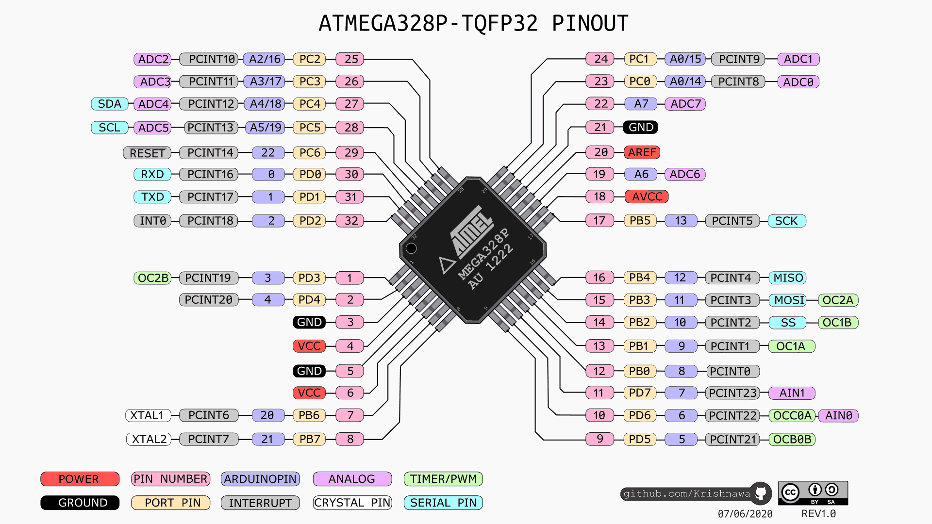
ATmega328P Pinout Reference
This pinout diagram shows every pin on the ATmega328P with its port name, Arduino pin number, and alternate functions. You will refer back to this throughout the course whenever you need to map between register names in code (like PB5 or PD2) and physical pin numbers on your board.
Download the full ATmega328P datasheet from Microchip (PDF) (archive copy). Keep it open as you work through this course. Every register name, bit field, and timing parameter comes directly from this document.
What We Are Building
Morse Code Beacon
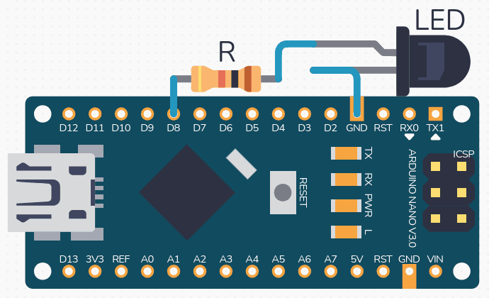
A bare-metal C program that encodes any string into International Morse Code and blinks it on the built-in LED connected to PB5 (pin 13). Dots, dashes, and inter-character gaps are all timed from a single delay function you write yourself. The entire build, flash, and fuse-check workflow runs from a single make flash command. No external wiring is needed for this first project.
The recommended path on Windows is MSYS2, which gives you a maintained avr-gcc and avrdude with a real installer rather than a portable build you have to wire up by hand.
Install MSYS2 from https://www.msys2.org and open the MSYS2 MINGW64 shell from the Start menu.
Update the package database (run twice if it asks you to close and reopen the shell):
Add C:\msys64\mingw64\bin to your system PATH so avr-gcc, avrdude, and make work from any terminal (PowerShell, cmd, VS Code).
Open a new terminal and verify:
Terminal window
avr-gcc--version
avrdude-?
Older guides point to WinAVR. That project was last released in 2010, ships only as a portable build that is awkward to put on PATH, and is no longer maintained. Avoid it unless you have a specific reason to use it.
Project Structure
Create a project directory with the following layout:
Directorymorse-beacon/
main.c
Makefile
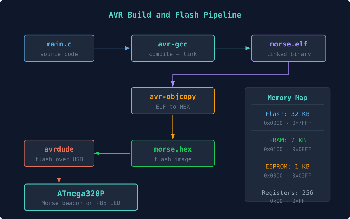
The Build and Flash Pipeline
The entire process from source code to running firmware follows a fixed pipeline. Each tool in the chain transforms the code into a form closer to what the hardware needs.
ATmega328P Memory Map
The ATmega328P has three separate memory spaces. Flash holds your program, SRAM holds variables at runtime, and EEPROM provides non-volatile storage for configuration data. Understanding these regions helps you interpret the avr-size output after compiling.
A Makefile automates the compile, link, convert, and flash steps so you only type make flash. Here is the complete Makefile for this project. Every line is intentional: MCU and F_CPU set the target, CFLAGS enables warnings and size optimization, and the flash target calls avrdude with the correct programmer and port.
The USB connection between your computer and the Arduino Nano looks like this electrically. The CH340 or FTDI chip on the Nano translates USB to TTL serial, which connects to the ATmega328P UART pins used by the bootloader during flashing.
+-----------+ USB cable +---------------------------+
The Makefile defaults to /dev/ttyUSB0, which is typical on Linux. On macOS the port is usually /dev/cu.usbserial-XXX, and on Windows it is something like COM3. Adjust the PORT variable to match your system.
Writing main.c
The firmware does three things: define a Morse code lookup table, implement a blocking delay using a busy loop calibrated to F_CPU, and loop through each character of a message string to blink the LED. The entire program fits comfortably under 1 KB of flash.
#defineF_CPU16000000UL
#include<avr/io.h>
#include<util/delay.h>
#include<string.h>
#include<ctype.h>
/* Morse timing (ms) */
#defineDOT_MS200
#defineDASH_MS600
#defineSYMBOL_GAP200 /* gap between dots/dashes in a letter */
#defineLETTER_GAP600 /* gap between letters */
#defineWORD_GAP1400 /* gap between words */
/* Morse lookup: A-Z encoded as strings of '.' and '-' */
constchar*message ="SAM"; /* Change to your name */
while (1) {
for (uint8_t i =0; i <strlen(message); i++) {
send_char(message[i]);
}
delay_ms(WORD_GAP *2); /* Long pause before repeating */
}
}
Compiling and Flashing
Connect the Arduino Nano to your computer via USB.
Find your serial port:
Terminal window
# Linux
ls/dev/ttyUSB*
# macOS
ls/dev/cu.usb*
# Windows (in Device Manager or)
mode
Update the PORT variable in your Makefile if needed.
Compile and flash:
Terminal window
makeflash
Watch the built-in LED on pin 13. It should blink your name in Morse code, pause, and repeat. No external wiring needed.
Reading the Fuse Bits
Fuse bits configure low-level chip behavior: clock source, brown-out detection, boot size, and more. They are stored in non-volatile memory separate from flash. Reading them helps you confirm the board is running from the external 16 MHz crystal as expected.
Terminal window
makefuses
Typical Nano/Uno fuse values:
Fuse
Value
Meaning
lfuse
0xFF
External full-swing crystal, slowly rising power
hfuse
0xDA
512-word bootloader, SPI programming enabled
efuse
0xFD
BOD at 2.7V
Understanding the Build Output
When you run make, avr-size prints a memory usage summary. The ATmega328P has 32 KB of flash, 2 KB of SRAM, and 1 KB of EEPROM. Your Morse beacon should use well under 1 KB of flash and only a few bytes of RAM. Getting comfortable reading these numbers early will save you from mysterious crashes later when projects grow larger.
AVR Memory Usage
----------------
Program: 512 bytes (1.6% Full)
Data: 9 bytes (0.4% Full)
Exercises
Change the message string to your full name and observe the LED pattern. Time it with a stopwatch to verify the dot and dash durations.
Add Morse codes for digits 0 through 9 to the lookup table. The pattern is systematic: “0” is -----, “1” is .----, and so on.
Modify the Makefile to produce a .bin file in addition to .hex. Use avr-objcopy -O binary for this.
Add an external LED on PB0 (pin 8): connect the LED’s longer leg (anode) to pin 8 through a 220 ohm resistor, and the shorter leg (cathode, the one with the flat edge on the LED body) to GND. Set PB0 as output with DDRB |= (1 << PB0) and blink both LEDs with inverted patterns: the built-in LED on while the external LED is off, and vice versa.
Summary
You now have a working bare-metal AVR development environment. You can compile C code with avr-gcc, convert it to Intel HEX format, flash it with avrdude, and read fuse bits. The Makefile gives you a repeatable one-command workflow. Every lesson that follows builds on this same toolchain, so make sure make flash works reliably before moving on.
Comments