The physical world is analog: temperature varies continuously, light intensity has infinite gradations, and sound is a smooth pressure wave. But your microcontroller processes discrete digital numbers. ADCs (Analog-to-Digital Converters) translate the analog world into numbers your code can work with, and DACs (Digital-to-Analog Converters) translate numbers back into analog voltages. Understanding how these conversions work helps you choose the right resolution, sample rate, and filtering for your application. #ADC #DAC #SignalConversion
ADC Fundamentals
What an ADC Does
An ADC takes a continuous analog voltage and produces a discrete digital number that represents that voltage. The process involves two steps:
Sampling: capturing the analog voltage at a specific instant in time
Quantization: mapping the captured voltage to the nearest digital value
Resolution
Resolution is the number of bits in the ADC’s output. It determines how finely the analog range is divided.
ADC Resolution
Number of Levels
Typical MCU
8-bit
256
ATmega328P (10-bit available)
10-bit
1,024
ATmega328P
12-bit
4,096
STM32F103, STM32F4, ESP32
16-bit
65,536
Some STM32H7 variants, external ADCs
24-bit
16,777,216
External ADCs (ADS1256 for precision measurement)
Least Significant Bit (LSB) Voltage
The LSB voltage is the smallest voltage change the ADC can detect:
where is the reference voltage and is the resolution in bits.
Example: A 12-bit ADC with :
This ADC can distinguish voltage changes as small as 0.8 mV. Any change smaller than this is lost in quantization.
ADC Transfer Function
The ADC produces a digital code based on the input voltage:
Example: What digital code does a 12-bit ADC (3.3V reference) produce for an input of 1.65V?
To convert back from a digital code to voltage:
In C:
// STM32 12-bit ADC, 3.3V reference
uint16_t adc_value =HAL_ADC_GetValue(&hadc1);
float voltage = (float)adc_value *3.3f/4096.0f;
Quantization Error
Because the ADC maps a continuous voltage to discrete levels, there is always a rounding error called quantization error. The maximum quantization error is LSB.
For a 12-bit ADC with 3.3V reference:
This is an inherent limitation. No amount of software can recover the information lost in quantization. If you need finer resolution, you need a higher-resolution ADC.
Other ADC Error Sources
Error
Description
Typical Magnitude
Offset error
Output is non-zero when input is 0V
1-2 LSB
Gain error
Slope of transfer function deviates from ideal
1-5 LSB
INL (Integral Nonlinearity)
Deviation of actual transfer function from ideal straight line
1-3 LSB
DNL (Differential Nonlinearity)
Variation in step size between adjacent codes
0.5-1 LSB
Noise
Random variation in readings
1-3 LSB (depends on layout, decoupling)
For most embedded applications, the dominant error is noise. Good PCB layout, proper decoupling capacitors, and software averaging significantly improve ADC accuracy.
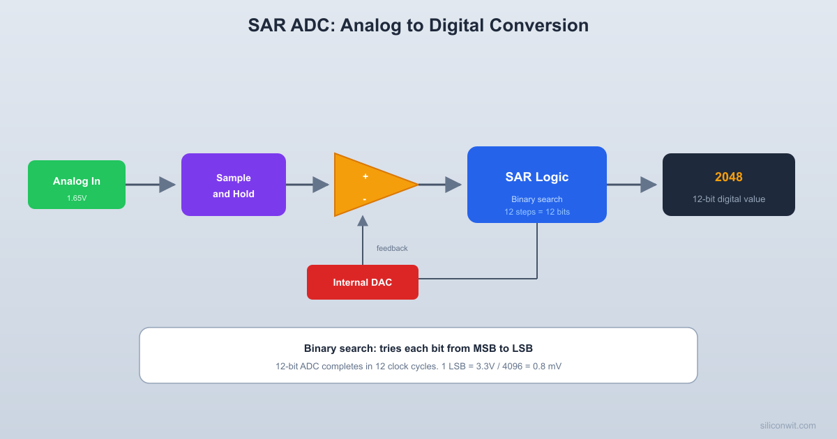
Successive Approximation ADC (SAR)
How It Works
The SAR ADC is the most common type in microcontrollers. It uses a binary search algorithm to find the digital code closest to the input voltage.
Components:
A DAC (internal)
A comparator
A SAR register (shift register with control logic)
A sample-and-hold circuit
  SAR ADC block diagram
  Vin ──→[S/H]──→(+)─┐                      │ Comparator  Vref ──→[DAC]──→(-)─┘              ▲           │              │       ┌───┴────┐              │       │  SAR   │              └───────┤Control │                      │Register│                      └───┬────┘                          │                     Digital Output                      (n-bit code)
  S/H = sample and hold  SAR = successive approximation register
Process for a 4-bit SAR ADC (simplified):
Sample and hold: The input voltage is captured and held steady on a capacitor.
Bit 3 (MSB) test: Set the DAC to 1000 (half of full scale). Compare: is the input greater than the DAC output? If yes, keep bit 3 as 1. If no, set bit 3 to 0.
Bit 2 test: Set the DAC to the current result + 0100 (quarter scale). Compare and keep or clear bit 2.
Bit 1 test: Set the DAC to the current result + 0010. Compare and keep or clear bit 1.
Bit 0 (LSB) test: Set the DAC to the current result + 0001. Compare and keep or clear bit 0.
Result: The 4-bit code in the SAR register is the closest digital representation of the input voltage.
Example: Converting 2.1V with a 4-bit ADC, 3.3V reference
Step
Test Value
DAC Voltage
Compare
Bit Value
SAR Register
1
1000
1.65V
2.1 > 1.65: yes
1
1000
2
1100
2.475V
2.1 > 2.475: no
0
1000
3
1010
2.0625V
2.1 > 2.0625: yes
1
1010
4
1011
2.269V
2.1 > 2.269: no
0
1010
Result: 1010 (decimal 10). Voltage: . The error is , which is less than one LSB ().
Why SAR Is Popular in MCUs
A 12-bit SAR ADC needs exactly 12 comparison cycles to produce a result. At a typical 14 MHz ADC clock (STM32F103), each conversion takes about 1 microsecond. This is fast enough for most sensor applications while using relatively little silicon area and power.
ADC Type
Speed
Resolution
Power
Used In
SAR
Medium (1-5 MSPS)
8-18 bits
Low
Most MCUs (STM32, ATmega, ESP32)
Delta-Sigma
Slow (10-1000 SPS)
16-24 bits
Low
Precision measurement, audio
Flash
Very fast (100+ MSPS)
4-8 bits
High
Video, radar, oscilloscopes
Pipeline
Fast (10-100 MSPS)
10-16 bits
Medium
Communications, imaging
Sampling and the Nyquist Theorem
The Sampling Theorem
The Nyquist-Shannon sampling theorem states:
To accurately reconstruct a signal, you must sample at a rate at least twice the highest frequency present in the signal.
The minimum sampling rate () is called the Nyquist rate.
Why This Matters
If you sample too slowly, high-frequency components in the signal fold back as lower frequencies, a phenomenon called aliasing. The aliased signal looks real but is an artifact of insufficient sampling.
Example: You are measuring a 50 Hz power line signal.
Sampling at 200 Hz: well above Nyquist (2 x 50 = 100 Hz). Signal reconstructed accurately.
Sampling at 80 Hz: below Nyquist. The 50 Hz signal aliases to appear as a 30 Hz signal (|80 - 50| = 30 Hz). Your measurement shows a wrong frequency.
Anti-Aliasing Filter
Before the ADC, an analog low-pass filter removes frequencies above . This prevents aliasing. A simple RC filter works for many embedded applications:
Example: For a 1 kHz ADC sample rate, the anti-aliasing filter should cut off below 500 Hz. With a 10K resistor: . A 33 nF capacitor would work.
Practical Sampling Rates
Application
Signal Bandwidth
Minimum Sample Rate
Typical Sample Rate
Temperature sensor
~1 Hz
2 Hz
10-100 Hz
Accelerometer
~500 Hz
1 kHz
1-10 kHz
Audio microphone
20 kHz
40 kHz
44.1 kHz or 48 kHz
Ultrasonic sensor
40 kHz
80 kHz
200 kHz
DAC: Digital-to-Analog Converter
What a DAC Does
A DAC takes a digital number and produces a proportional analog voltage:
R-2R Ladder DAC
The simplest DAC architecture uses only two resistor values: R and 2R. This makes it inexpensive and easy to build from discrete components.
4-bit R-2R ladder:
  R-2R ladder DAC (4-bit)
  D3       D2       D1       D0  │        │        │        │ [2R]     [2R]     [2R]     [2R]  │        │        │        │  ├──[R]───├──[R]───├──[R]───├──[2R]─→GND  │  └──→ Vout (to op-amp buffer)
  D3 contributes Vref/2  D2 contributes Vref/4  D1 contributes Vref/8  D0 contributes Vref/16
Each digital input (D0-D3) connects to either VCC (for a 1) or GND (for a 0). The resistor network creates a weighted sum of the inputs. D3 (MSB) contributes twice as much voltage as D2, which contributes twice as much as D1, and so on.
How it works conceptually:
For a 4-bit DAC with and code = 1010 (decimal 10):
DACs in Microcontrollers
Not all MCUs have a built-in DAC. The STM32F103 does not have one, but the STM32F4 and STM32F7 families have 12-bit DACs. The ESP32 has two 8-bit DACs.
MCU
DAC
Resolution
Channels
ATmega328P
None
-
-
STM32F103
None
-
-
STM32F407
Yes
12-bit
2
ESP32
Yes
8-bit
2
PWM as a Pseudo-DAC
Concept
If your MCU does not have a hardware DAC, you can approximate an analog output using PWM (Pulse Width Modulation) combined with a low-pass filter.
A PWM signal switches between 0V and VCC at a fixed frequency. The duty cycle determines the average voltage:
Duty Cycle
Average Voltage (3.3V VCC)
0%
0V
25%
0.825V
50%
1.65V
75%
2.475V
100%
3.3V
Filtering PWM to Analog
A raw PWM signal is a square wave. To get a smooth analog voltage, pass it through an RC low-pass filter:
MCU PWM Pin ──[R]──┬──→ Analog Output
│
[C]
│
GND
Choose the filter cutoff frequency well below the PWM frequency:
PWM frequency: 20 kHz (typical for LED dimming or audio)
Filter cutoff: 200 Hz ( of PWM frequency)
Calculation:, (use 100 nF)
The lower the cutoff relative to the PWM frequency, the smoother the output, but the slower the response to changes in duty cycle.
PWM Resolution
The effective resolution of PWM-as-DAC depends on the timer resolution and frequency:
Example: STM32F103 at 72 MHz, PWM frequency 20 kHz:
That is about 11.8 bits of resolution (), which is comparable to a 12-bit DAC. Increasing the PWM frequency reduces the number of steps (and resolution). Decreasing it gives more steps but requires a slower filter.
Practical Exercises
Exercise 1: ADC Voltage Calculation
Your STM32 has a 12-bit ADC with a 3.3V reference. The ADC reads a value of 2730. What is the input voltage?
Solution
In C:
float voltage =2730.0f*3.3f/4096.0f; // 2.199V
Exercise 2: Resolution Comparison
You need to measure a 0 to 5V signal with a precision of at least 5 mV. What is the minimum ADC resolution required?
Solution
The LSB voltage must be less than or equal to 5 mV:
, so a 10-bit ADC is sufficient.
With 10 bits: , which meets the 5 mV requirement.
Exercise 3: Sampling Rate
You are measuring vibration on a motor. The vibration frequency range is 10 Hz to 2 kHz. What is the minimum sampling rate? What rate would you choose in practice?
Solution
Nyquist rate: Hz minimum.
In practice, use 3 to 5 times the Nyquist rate for better signal quality: 10 to 20 kHz. A common choice would be 10 kHz.
You would also need an anti-aliasing filter with a cutoff around 2 to 3 kHz.
Exercise 4: PWM DAC Design
You want to generate a 0 to 3.3V analog signal using PWM on an ATmega328P running at 16 MHz. Using an 8-bit timer (256 levels), what is the PWM frequency? How many voltage levels can you produce?
Solution
PWM frequency:
Voltage levels: 256 (0 to 255), giving a voltage step of .
For filtering, choose a cutoff well below 62.5 kHz. At 625 Hz (1/100 of PWM): , (use 27 nF or 33 nF).
How This Connects to Embedded Programming
Sensor Reading
Every analog sensor (temperature, light, pressure, current) connects to an ADC input. When you call analogRead() on Arduino or HAL_ADC_GetValue() on STM32, the SAR ADC runs through its binary search, and you get a digital code. Knowing the reference voltage and resolution lets you convert that code to engineering units.
Oversampling and Averaging
By taking multiple ADC samples and averaging, you can reduce noise and effectively increase resolution. Averaging 16 samples of a 12-bit ADC gives approximately 14 bits of effective resolution. This works because random noise averages out while the signal does not.
PWM for Analog Output
LED brightness, motor speed, and audio output are all commonly controlled with PWM. The timer/counter peripheral (Lesson 5) generates the PWM signal, and an external filter (or the mechanical inertia of the motor, or the persistence of vision for LEDs) smooths it into an effective analog value.
DMA and ADC
On STM32, the ADC can be triggered by a timer and its results transferred to memory by DMA, completely bypassing the CPU. This allows continuous high-speed sampling without any CPU involvement, exactly because the ADC is a self-contained hardware block operating on the bus system described in Lesson 6.
Summary
Concept
Key Takeaway
ADC resolution
More bits = finer voltage discrimination. 12-bit is standard in most MCUs.
LSB voltage
. Determines the smallest detectable voltage change.
Quantization error
Inherent, max LSB. Cannot be eliminated, only reduced by higher resolution.
SAR ADC
Binary search algorithm. Needs clock cycles for bits. Most common MCU ADC type.
Nyquist theorem
Sample at least to avoid aliasing.
R-2R DAC
Simple resistor network for digital-to-analog conversion.
PWM as DAC
Timer-generated square wave plus RC filter. Resolution depends on timer frequency.
In the next and final lesson, you will see how all of these building blocks (logic gates, memory, buses, ADC) come together inside a microcontroller CPU.
Comments