I2C (also called TWI on Atmel chips) lets you connect dozens of sensors and peripherals with just two wires. In this lesson you will implement the ATmega328P TWI interface from scratch, handling start conditions, addressing, ACK/NACK responses, and multi-byte reads. The project is a mini weather station: a BME280 sensor provides temperature, humidity, and barometric pressure readings, and the firmware displays all three values on the SSD1306 OLED from the previous lesson. Two different peripherals sharing two wires, all driven by code you wrote. #I2C #BME280 #WeatherStation
What We Are Building
Mini Weather Station
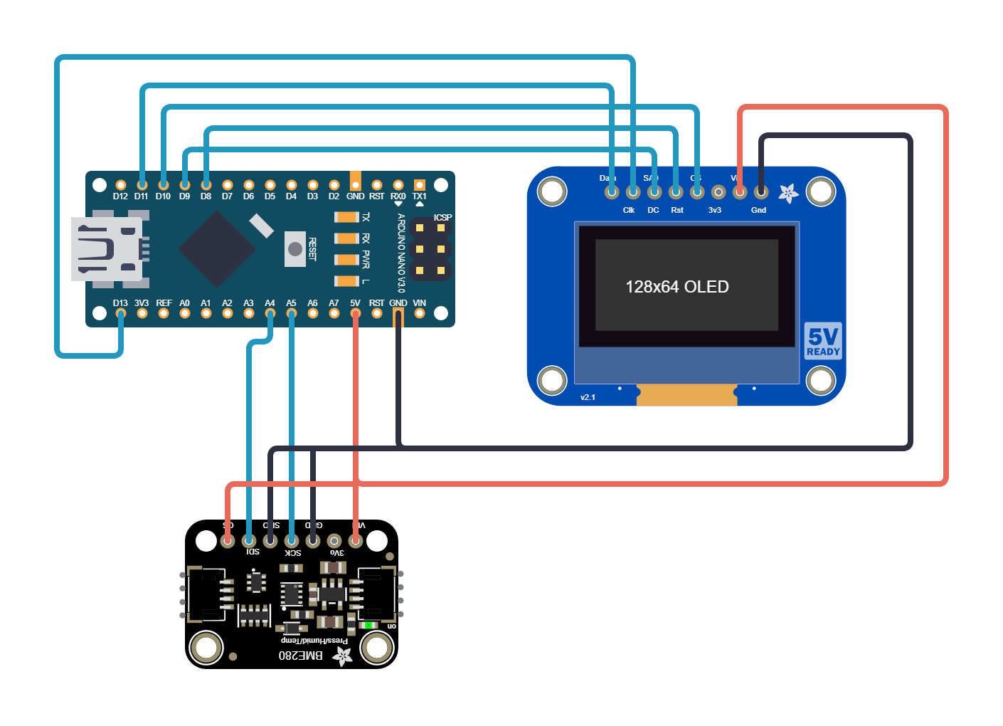
A BME280 environmental sensor connected over I2C provides temperature (0.01 C resolution), relative humidity (0.008% resolution), and barometric pressure (0.18 Pa resolution). The firmware reads all three measurements every 2 seconds, applies the BME280 compensation formulas, and renders the results on the SSD1306 OLED display. The OLED is driven over SPI (from Lesson 6), and the BME280 over I2C, showing both buses working together.
Project specifications:
Parameter
Value
MCU
ATmega328P (on Arduino Nano or Uno)
Sensor
BME280 (I2C address 0x76 or 0x77)
Display
SSD1306 128x64 OLED (SPI)
I2C clock
100 kHz (standard mode)
I2C pins
SDA (PC4), SCL (PC5)
Update rate
0.5 Hz (every 2 seconds)
Data shown
Temperature (C), Humidity (%), Pressure (hPa)
Parts for This Lesson
Ref
Component
Quantity
Notes
1
Arduino Nano or Uno (ATmega328P)
1
From previous lessons
2
Breadboard
1
From previous lessons
3
BME280 breakout module
1
I2C variant with pull-ups on board
4
SSD1306 OLED 128x64 (SPI)
1
From Lesson 6
5
Jumper wires
~4
For I2C connections
I2C Protocol Fundamentals
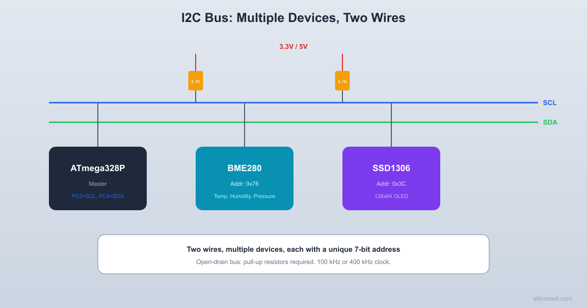
I2C is a two-wire synchronous protocol. SDA carries data and SCL carries the clock. Both lines are open-drain with external pull-up resistors (typically 4.7K).
  I2C Bus with two devices:
       VCC           VCC        |             |      [4.7K]        [4.7K]        |             |  SDA --+------+------+------+--        |      |             |  SCL --+--+---+--+----------+--           |      |          |      +----+--+  ++---------++      |ATmega |  | BME280   ||  SSD1306      |328P   |  | addr:    ||  addr:      |(master)|  | 0x76     ||  0x3C      +--------+  +----------++----------+
  Both lines are open-drain:  devices can only pull LOW.  Pull-ups restore HIGH when released.
The master generates the clock and initiates all communication. A transaction starts with a START condition (SDA falls while SCL is high), followed by a 7-bit address plus a read/write bit, then one or more data bytes, and ends with a STOP condition (SDA rises while SCL is high). For a comparison of I2C with SPI and other bus protocols, see Digital Electronics: Bus Architecture and Interfaces.
I2C Transaction Anatomy
Step
SDA
SCL
Description
START
High to Low
High
Master signals start
Address (7 bits) + R/W
Data
Clock pulses
Master sends slave address
ACK
Slave pulls low
Clock pulse
Slave acknowledges
Data byte
Data
Clock pulses
8 bits, MSB first
ACK/NACK
Receiver pulls low (or not)
Clock pulse
Acknowledge each byte
STOP
Low to High
High
Master signals stop
TWI Registers on ATmega328P
An I2C write transaction to the BME280 follows this sequence of bus states. Each step produces a status code in TWSR that your driver must check.
The ATmega328P calls its I2C hardware TWI (Two-Wire Interface). Five registers control it. TWBR sets the bit rate (clock speed). TWCR is the control register where you trigger actions by writing specific bit combinations. TWSR holds status codes that tell you what happened after each operation. TWDR is the data register for send/receive. TWAR sets the slave address (only used in slave mode).
Register
Purpose
TWBR
Bit Rate Register: SCL frequency = F_CPU / (16 + 2 * TWBR * prescaler)
Status: 5-bit status code in upper bits, prescaler in lower 2 bits
TWDR
Data Register: write to send, read after receive
TWAR
Slave Address Register (not used in master mode)
Setting the I2C Clock Speed
For 100 kHz standard mode with a 16 MHz system clock and prescaler 1:
TWBR = ((F_CPU / SCL_FREQ) - 16) / 2
TWBR = ((16000000 / 100000) - 16) / 2 = 72
TWI Driver Implementation
#defineF_CPU16000000UL
#defineTWI_FREQ100000UL
#include<avr/io.h>
#include<stdlib.h>
#include<util/delay.h>
staticvoidtwi_init(void)
{
TWSR =0; /* Prescaler = 1 */
TWBR = ((F_CPU / TWI_FREQ) -16) /2;
TWCR = (1<< TWEN); /* Enable TWI */
}
staticuint8_ttwi_start(void)
{
TWCR = (1<< TWINT) | (1<< TWSTA) | (1<< TWEN);
while (!(TWCR & (1<< TWINT)));
return (TWSR &0xF8); /* Status code */
}
staticvoidtwi_stop(void)
{
TWCR = (1<< TWINT) | (1<< TWSTO) | (1<< TWEN);
while (TWCR & (1<< TWSTO)); /* Wait for stop to complete */
}
staticuint8_ttwi_write(uint8_tdata)
{
TWDR = data;
TWCR = (1<< TWINT) | (1<< TWEN);
while (!(TWCR & (1<< TWINT)));
return (TWSR &0xF8);
}
staticuint8_ttwi_read_ack(void)
{
TWCR = (1<< TWINT) | (1<< TWEA) | (1<< TWEN);
while (!(TWCR & (1<< TWINT)));
return TWDR;
}
staticuint8_ttwi_read_nack(void)
{
TWCR = (1<< TWINT) | (1<< TWEN);
while (!(TWCR & (1<< TWINT)));
return TWDR;
}
TWI Status Codes
Code
Meaning
0x08
START condition transmitted
0x10
Repeated START transmitted
0x18
SLA+W transmitted, ACK received
0x20
SLA+W transmitted, NACK received
0x28
Data transmitted, ACK received
0x40
SLA+R transmitted, ACK received
0x50
Data received, ACK returned
0x58
Data received, NACK returned
Reading the BME280
The BME280 uses a register-based interface. To read a register, you send a write transaction with the register address, then a repeated start followed by a read transaction. The sensor has a block of calibration data in registers 0x88 through 0xA1 and 0xE1 through 0xF0. Raw measurement data lives in registers 0xF7 through 0xFE (8 bytes for pressure, temperature, and humidity). The compensation algorithm uses integer arithmetic defined in the BME280 datasheet.
/* Humidity oversampling x1 (must be set before ctrl_meas) */
bme280_write_reg(0xF2, 0x01);
/* Temperature x1, Pressure x1, Normal mode */
bme280_write_reg(0xF4, 0x27);
/* Standby 1000ms, filter off */
bme280_write_reg(0xF5, 0xA0);
}
Compensation Formulas
The BME280 datasheet provides integer compensation routines that convert raw ADC values into physical units. These use 32-bit arithmetic and a shared variable (t_fine) that links the temperature compensation to pressure and humidity compensation. The formulas are complex but they come directly from Bosch’s reference implementation.
v = v - (((((v >>15) * (v >>15)) >>7) * ((int32_t)cal.dig_H1)) >>4);
v = (v <0) ?0: v;
v = (v >419430400) ?419430400: v;
return (uint32_t)(v >>12); /* Result in Q22.10 format (divide by 1024 for %) */
}
Putting It All Together
The main loop reads all eight data bytes from the BME280 in a single burst, applies the compensation formulas, formats the results as strings, and renders them on the OLED. The OLED driver from Lesson 6 handles the display update. Temperature is shown in degrees Celsius, humidity as a percentage, and pressure in hectopascals (which equals millibars).
The I2C START and STOP conditions are defined by SDA transitions while SCL is high. During normal data transfer, SDA only changes while SCL is low.
  I2C START and STOP conditions:
  SDA: ----+         +----           |         |           +---------+  SCL: ------+     +------             |     |             +-----+        START           STOP      (SDA falls     (SDA rises      while SCL      while SCL      is HIGH)       is HIGH)
I2C problems are common and can be frustrating. Here are the most frequent issues and how to solve them.
Problem
Likely Cause
Fix
No ACK from sensor
Wrong address, wiring error
Check SDA/SCL connections, try both 0x76 and 0x77
Bus stuck (SDA held low)
Sensor confused by interrupted transaction
Toggle SCL manually 9 times, then send STOP
Corrupted data
Missing pull-ups
Add 4.7K pull-ups on SDA and SCL to VCC
Intermittent failures
Long wires, noise
Keep wires under 30 cm, add decoupling capacitor near sensor
All readings zero
Wrong register address or oversampling off
Verify ctrl_meas and ctrl_hum register values
Exercises
Add error checking to the TWI driver: verify the status code after each operation and return an error code if something unexpected happens. Implement a retry mechanism.
Display the pressure as altitude using the barometric formula: altitude = 44330 * (1 - (P/P0)^0.1903) where P0 is sea-level pressure (101325 Pa).
Log all three readings over UART (from Lesson 5) in CSV format alongside the OLED display, so you can capture data on a PC.
Add a second I2C device (for example a BH1750 light sensor at address 0x23) and display its readings on the fourth line of the OLED.
Summary
You now understand the I2C protocol at the register level: start/stop conditions, addressing, ACK/NACK handshaking, and burst reads. You implemented a complete TWI driver for the ATmega328P and used it to interface with the BME280, one of the most capable environmental sensors available. The weather station combines I2C input (BME280) with SPI output (OLED), demonstrating how multiple bus protocols coexist in a single project. I2C’s simplicity (two wires, addressable devices) makes it the default choice for most sensor interfacing.
Comments