Most STM32 tutorials jump straight into HAL-generated code, skipping everything that happens before main() runs. In this lesson, you will install the complete ARM toolchain from scratch, flash a breathing LED onto the Blue Pill board, and trace the entire boot sequence from the vector table through startup assembly to your C code. Understanding these foundations makes every future debugging session faster and every peripheral configuration clearer. #STM32 #ARM #Toolchain
What We Are Building
Breathing LED with HSE Clock and Timer PWM
A smooth breathing LED that ramps brightness up and down using hardware PWM driven by a general-purpose timer. The HSE crystal provides an accurate 72 MHz system clock through the PLL, and the timer generates a PWM signal that sweeps duty cycle from 0% to 100% and back. No blocking delays; the LED breathes entirely in hardware while the CPU is free.
You should see output ending with something like Info : stm32f1x.cpu: hardware has 6 breakpoints, 4 watchpoints. Press Ctrl+C to exit.
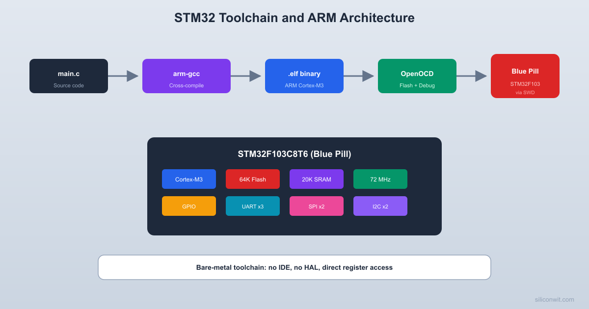
ARM Cortex-M3 Architecture Overview
The STM32F103 is built around the ARM Cortex-M3 core. Unlike application processors (Cortex-A), the Cortex-M series is designed specifically for microcontrollers: deterministic interrupt latency, a built-in NVIC (Nested Vectored Interrupt Controller), Thumb-2 instruction set only, and hardware-assisted exception handling. Understanding a few key architectural concepts will help you write better firmware and debug problems more effectively.
Memory Map
The Cortex-M3 uses a fixed 4 GB address space divided into well-defined regions:
Address Range
Region
STM32F103 Usage
0x0000_0000 - 0x1FFF_FFFF
Code
Flash (aliased from 0x0800_0000)
0x2000_0000 - 0x3FFF_FFFF
SRAM
20 KB SRAM
0x4000_0000 - 0x5FFF_FFFF
Peripherals
GPIO, UART, SPI, timers, etc.
0xE000_0000 - 0xE00F_FFFF
System
NVIC, SysTick, debug registers
Vector Table
The Cortex-M3 boot sequence reads the vector table, loads the initial stack pointer, and jumps to the reset handler. This all happens in hardware before any of your code runs.
  Cortex-M3 boot sequence:
  1. Read word at 0x0000_0000 --> MSP     (set stack pointer)
  2. Read word at 0x0000_0004 --> PC     (jump to Reset_Handler)
  3. Reset_Handler executes:     +---------------------------+     | Copy .data flash -> SRAM  |     | Zero .bss section         |     | Call SystemInit()         |     | Call main()               |     +---------------------------+
The very first thing the Cortex-M3 reads after reset is the vector table, stored at address 0x0000_0000 (which maps to the start of flash at 0x0800_0000). The first entry is the initial stack pointer value. The second entry is the reset handler address. The remaining entries are exception and interrupt handler addresses.
(uint32_t)TIM2_IRQHandler, /* TIM2 global interrupt */
/* ... more peripheral interrupts ... */
};
Startup Code
The startup code runs before main(). It copies initialized data from flash to SRAM (the .data section), zeros out uninitialized global variables (the .bss section), calls any C++ constructors (if applicable), sets up the FPU (on Cortex-M4F), and finally calls main(). On the STM32F103, CMSIS provides SystemInit() which configures the clock tree before main() begins.
Linker Script
The linker script tells the toolchain where to place code and data in memory:
/* Minimal STM32F103C8T6 linker script excerpt */
MEMORY
{
FLASH (rx) : ORIGIN = 0x08000000, LENGTH = 64K
RAM (rwx) : ORIGIN = 0x20000000, LENGTH = 20K
}
SECTIONS
{
.isr_vector : {
KEEP(*(.isr_vector))
} > FLASH
.text : {
*(.text*)
*(.rodata*)
} > FLASH
.data : {
_sdata = .;
*(.data*)
_edata = .;
} > RAM AT > FLASH
.bss : {
_sbss = .;
*(.bss*)
_ebss = .;
} > RAM
}
_estack = ORIGIN(RAM) + LENGTH(RAM);
Building the Breathing LED
Project Structure
Directorybreathing-led/
Directorysrc/
main.c
startup_stm32f103.s
system_stm32f1xx.c
Directoryinclude/
stm32f103xb.h
system_stm32f1xx.h
STM32F103C8Tx_FLASH.ld
Makefile
openocd.cfg
Clock Configuration (HSE + PLL = 72 MHz)
The Blue Pill has an 8 MHz crystal connected to the HSE pins. We configure the PLL to multiply this by 9, giving us a 72 MHz system clock.
  Clock configuration:
  HSE crystal    PLL          SYSCLK  +-------+   +------+     +--------+  | 8 MHz |-->| x9   |---->| 72 MHz |  +-------+   +------+     +---+----+                                |                 +--------------+                 |         AHB prescaler /1                 v              |           +----------+    +---+----+           | SYSCLK   |   | 72 MHz |           | 72 MHz   |   +---+----+           +----------+       |                         +----+----+                         |         |                    APB2 /1   APB1 /2                    72 MHz    36 MHz                    (GPIO,    (TIM2-4,                     SPI1,     I2C,                     USART1)   USART2)
The AHB bus runs at 72 MHz, APB2 at 72 MHz, and APB1 at 36 MHz (maximum for APB1). The USB peripheral needs 48 MHz, which comes from the 72 MHz PLL output divided by 1.5.
The LED on PA0 should now smoothly ramp up and down in brightness. If you see it blinking instead of breathing, check that the PWM output pin (PA0) is correctly wired and that the timer configuration matches the code above.
Exploring with STM32CubeMX
STM32CubeMX is ST’s graphical configuration tool. It generates initialization code for clocks, peripherals, and pin assignments. While we wrote bare-register code above, CubeMX is invaluable for quickly checking pin alternate functions, visualizing the clock tree, and generating a starting point for complex configurations.
Open STM32CubeMX and create a new project for STM32F103C8T6.
Click the Clock Configuration tab. Set HSE to 8 MHz, enable PLL, set the multiplier to x9, and verify the system clock shows 72 MHz. Notice how APB1 is limited to 36 MHz.
Back in the Pinout tab, click PA0 and set it to TIM2_CH1. Notice the pin turns green, indicating a valid alternate function assignment.
Under Timers > TIM2, set Channel 1 to “PWM Generation CH1”. Set the prescaler and auto-reload values to match our 1 kHz PWM configuration.
Click Generate Code to see the HAL-based equivalent. Compare the generated MX_TIM2_Init() function with our register-level code above. The registers being written are the same; HAL wraps them in structures and error checking.
CMSIS and Device Headers
CMSIS (Cortex Microcontroller Software Interface Standard) provides a standardized way to access Cortex-M core registers and peripherals. The device header file (stm32f103xb.h) defines register addresses, bit field masks, and peripheral structures so you can write TIM2->CCR1 instead of *(volatile uint32_t*)0x40000034. Every STM32 project uses these headers, whether you write bare-register code or use HAL.
You can get the CMSIS and device headers from two sources:
STM32CubeF1 package: Download from ST’s website or clone https://github.com/STMicroelectronics/STM32CubeF1. The headers are in Drivers/CMSIS/Device/ST/STM32F1xx/Include/.
Generated by CubeMX: When you generate code, CubeMX copies the necessary headers into your project.
What You Have Learned
Lesson 1 Complete
Toolchain skills:
Installed arm-none-eabi-gcc, OpenOCD, and STM32CubeMX
Comments