Buttons bounce. Interrupts fire at unpredictable times. And if you accidentally call a blocking function inside an ISR, your entire system locks up with no error message. These three facts make interrupt management one of the trickiest parts of RTOS programming. In this lesson you will build a four-button input system that handles all of these problems correctly. Hardware interrupts trigger short ISR handlers that notify tasks using ISR-safe APIs, software timers debounce the button signals, and critical sections protect any shared data. Each button controls a different LED pattern, and you will see exactly what happens when you break the rules on purpose. #FreeRTOS #Interrupts #SoftwareTimers
What We Are Building
Debounced Multi-Button Input System
Four push buttons connected to GPIO interrupts. Each ISR uses xSemaphoreGiveFromISR() to wake a handler task without blocking. FreeRTOS software timers implement a 50 ms debounce window for each button. A pattern task reads the debounced button states and drives four LEDs with different blink patterns. Critical sections protect a shared configuration structure that both the button handler and pattern task access.
Project specifications:
Parameter
Value
MCU
STM32 Blue Pill or ESP32 DevKit
RTOS
FreeRTOS
Buttons
4 GPIO inputs with hardware interrupts
Debounce method
FreeRTOS software timers (50 ms period)
ISR technique
Deferred processing via binary semaphores
LEDs
4 (one per button, each with unique blink pattern)
Critical sections
taskENTER_CRITICAL / taskEXIT_CRITICAL
Timer service task
Runs at configTIMER_TASK_PRIORITY
Parts List
Ref
Component
Quantity
Notes
U1
STM32 Blue Pill or ESP32 DevKit
1
Reuse from prior courses
SW1, SW2, SW3, SW4
Tactile push button
4
GPIO interrupt sources
D1, D2, D3, D4
LED (any color)
4
Visual output per button
R1, R2, R3, R4
330 ohm resistor
4
LED current limiters
R5, R6, R7, R8
10k ohm resistor
4
Button pull-down (if needed)
-
Breadboard and jumper wires
1 set
For prototyping
The ISR Problem
An interrupt service routine must finish quickly. The hardware freezes the normal program flow, saves context to the stack, and jumps into your ISR. While your ISR is running, no other interrupt of equal or lower priority can fire, and the RTOS scheduler cannot perform a context switch. If your ISR takes too long, you miss other interrupts, starve tasks, and destroy real-time guarantees.
On ARM Cortex-M processors (including the STM32F103 on the Blue Pill), the situation is even more constrained. The processor enters Handler mode during an ISR. The FreeRTOS scheduler relies on the PendSV and SysTick exceptions to switch tasks, and both of these run at the lowest interrupt priority. If your ISR blocks or loops waiting for something, PendSV never gets a chance to run, and the scheduler is locked out completely.
This means you cannot call any FreeRTOS function that might block from inside an ISR:
/* ALL OF THESE WILL HANG THE SYSTEM IF CALLED FROM AN ISR */
xQueueSend(queue, &data, portMAX_DELAY); /* Blocks if queue full */
xSemaphoreTake(sem, portMAX_DELAY); /* Blocks if unavailable */
vTaskDelay(pdMS_TO_TICKS(10)); /* Blocks for 10 ms */
xEventGroupWaitBits(grp, bits, ...); /* Blocks until bits set */
The kernel detects some of these violations through configASSERT, but only if you have assertions enabled. Without them, the system simply freezes with no indication of what went wrong.
Deferred Interrupt Processing
────────────────────────────────────────
Hardware ISR (fast) Task (slow)
───────── ────────── ───────────
Button ──IRQ──► Ack interrupt
Give semaphore ─► Wake from block
Return Read GPIO
(< 1 us) Debounce logic
Update LEDs
Log event
(runs at task
priority)
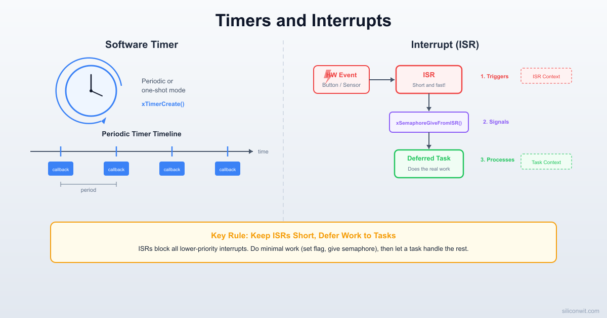
The solution is deferred interrupt processing: the ISR does the absolute minimum (acknowledge the hardware, signal a task) and returns immediately. A regular FreeRTOS task picks up where the ISR left off and does the actual work.
ISR-Safe API Calls
Every blocking FreeRTOS function has a counterpart that is safe to call from an ISR. These “FromISR” variants never block. They either succeed immediately or return an error code.
Regular API
ISR-Safe Variant
xSemaphoreGive()
xSemaphoreGiveFromISR()
xQueueSend()
xQueueSendFromISR()
xQueueReceive()
xQueueReceiveFromISR()
xTaskNotifyGive()
vTaskNotifyGiveFromISR()
xEventGroupSetBits()
xEventGroupSetBitsFromISR()
xTimerStartFromISR()
xTimerStartFromISR()
xTimerResetFromISR()
xTimerResetFromISR()
  Timer Service Task Architecture  ────────────────────────────────────────  App Code          Timer Queue        Timer Task  ────────          ───────────        ──────────  xTimerStart() ──► ┌─────────┐  xTimerStop()  ──► │ command  │ ──► Process cmd  xTimerReset() ──► │ queue    │     Call callback                    └─────────┘     (timer context,                                     not ISR context)
  Timer callbacks run in the Timer Service Task  at configTIMER_TASK_PRIORITY. They must not  block, but they CAN call regular (non-ISR)  FreeRTOS APIs.
All FromISR functions share a common pattern. They accept a pointer to a BaseType_t variable called pxHigherPriorityTaskWoken. The kernel sets this variable to pdTRUE if the API call unblocked a task with a higher priority than the currently running task. After your ISR finishes its work, you check this flag and call portYIELD_FROM_ISR() to request an immediate context switch:
/* If we woke a higher-priority task, request a context switch */
portYIELD_FROM_ISR(xHigherPriorityTaskWoken);
}
Without portYIELD_FROM_ISR, the woken task would not run until the next SysTick interrupt, adding up to one full tick period of latency. With the yield request, the context switch happens immediately when the ISR returns.
Deferred Interrupt Processing
The deferred processing pattern splits interrupt handling into two parts: a short ISR that signals, and a task that does the real work.
Hardware ISR Handler Task
│ │ │
│──interrupt──────>│ │ (blocked on semaphore)
│ │──GiveFromISR()──────>│
│ │──YIELD_FROM_ISR() │
│ │<─return──────────────│ (wakes up)
│ │ │──process event
│ │ │──take semaphore (block)
Here is the complete flow for a single button:
/* Binary semaphore for deferred processing */
SemaphoreHandle_t xButtonSem;
/* ISR: runs in interrupt context, must be very short */
voidEXTI0_IRQHandler(void) {
BaseType_t xWoken = pdFALSE;
EXTI->PR= EXTI_PR_PR0; /* Clear interrupt flag */
xSemaphoreGiveFromISR(xButtonSem, &xWoken);
portYIELD_FROM_ISR(xWoken);
}
/* Handler task: runs in task context, can call any FreeRTOS API */
voidvButtonHandlerTask(void*pvParameters) {
for (;;) {
/* Block until the ISR signals us */
if (xSemaphoreTake(xButtonSem, portMAX_DELAY)== pdTRUE) {
/* Safe to call blocking functions here */
uint8_t pin_state =read_gpio(BUTTON_PIN);
if (pin_state) {
/* Process the button press */
update_led_pattern();
}
}
}
}
A binary semaphore works perfectly for this pattern because it latches. If the button is pressed multiple times while the handler task is busy, the semaphore simply stays “given.” The handler task processes one event, takes the semaphore again, and if more presses occurred it wakes up immediately. No presses are lost, though rapid presses are coalesced into one event, which is actually desirable for buttons.
Critical Sections
When a task and an ISR both access the same data, you need a way to prevent the ISR from firing in the middle of a task’s read-modify-write operation. Mutexes do not work here because an ISR cannot take a mutex (it would block). FreeRTOS provides critical sections for this purpose.
/* Shared structure accessed by both a task and ISRs */
taskENTER_CRITICAL() disables all interrupts up to and including configMAX_SYSCALL_INTERRUPT_PRIORITY. Interrupts with a priority numerically lower than this threshold (meaning higher urgency on Cortex-M) are not disabled and can still fire. This is important for very high-priority interrupts like motor control or safety shutdown handlers that must never be delayed.
Critical sections are reference counted, so they nest safely:
taskENTER_CRITICAL(); /* nesting depth = 1 */
/* ... */
taskENTER_CRITICAL(); /* nesting depth = 2 */
/* ... */
taskEXIT_CRITICAL(); /* nesting depth = 1, interrupts still off */
The golden rule: keep critical sections as short as possible. Every tick spent inside a critical section is a tick where no other interrupt can fire and no task can be scheduled. Copy the data you need into local variables, exit the critical section, then do the heavy processing on the local copies.
ARM Cortex-M priority numbering is backwards compared to what most people expect. A lower priority number means a higher urgency. Priority 0 is the highest priority interrupt on the system, and priority 15 (on a 4-bit priority implementation like the STM32F103) is the lowest.
This threshold divides all interrupts into two groups:
Priority Range
Behavior
0 to 4 (above threshold)
Cannot call any FreeRTOS API. These interrupts are never disabled by critical sections or the scheduler. Use for ultra-low-latency handlers (motor control, safety).
5 to 15 (at or below threshold)
Can safely call FromISR functions. These are masked during critical sections.
A common mistake is setting a GPIO interrupt to priority 2 and then calling xSemaphoreGiveFromISR from it. The interrupt fires during a critical section, the kernel’s internal data structures are in an inconsistent state, and the system crashes. Always verify that any interrupt calling FreeRTOS APIs has a priority number greater than or equal toconfigLIBRARY_MAX_SYSCALL_INTERRUPT_PRIORITY.
On the STM32, you set interrupt priority like this:
/* Set EXTI0 interrupt to priority 6 (safe for FreeRTOS API calls) */
NVIC_SetPriority(EXTI0_IRQn, 6);
NVIC_EnableIRQ(EXTI0_IRQn);
On the ESP32, the situation is simpler. ESP-IDF manages interrupt allocation, and you specify the interrupt level when registering:
gpio_install_isr_service(ESP_INTR_FLAG_LEVEL1);
Level 1 is the default for most GPIO interrupts and is compatible with FreeRTOS API calls.
FreeRTOS Software Timers
A software timer lets you schedule a function to run after a specified delay, without creating a dedicated task for the timing. Software timers are managed by the timer service task (also called the timer daemon), which FreeRTOS creates automatically when you use any timer API.
Creating a Timer
#include"timers.h"
TimerHandle_t xDebounceTimer;
/* Callback function: runs in the timer service task context */
voidvDebounceCallback(TimerHandle_txTimer) {
/* This runs as a regular task, NOT in ISR context */
uint8_t pin_state =read_gpio(BUTTON_PIN);
if (pin_state) {
/* Button is still pressed after debounce period */
The second parameter on each of these calls is a block time. Timer commands are sent to the timer service task via a command queue. If the queue is full, the calling task blocks for up to this duration. In practice, with a reasonable configTIMER_QUEUE_LENGTH (10 is a good default), the queue is almost never full.
Timer Service Task Configuration
The timer callback runs inside the timer service task, not inside the task that created the timer, and not in ISR context. This means callbacks can call any FreeRTOS API, but they must not block for long because all timer callbacks share the same task. A callback that calls vTaskDelay(1000) would delay every other timer callback by one second.
FreeRTOSConfig.h
#defineconfigUSE_TIMERS1
#defineconfigTIMER_TASK_PRIORITY2 /* Higher than most app tasks */
#defineconfigTIMER_QUEUE_LENGTH10 /* Max pending timer commands */
#defineconfigTIMER_TASK_STACK_DEPTH256 /* Stack words for timer task */
Set configTIMER_TASK_PRIORITY high enough that timer callbacks run promptly. If the timer task priority is lower than a CPU-bound application task, timer callbacks could be delayed indefinitely.
Debouncing with Software Timers
Mechanical push buttons do not produce a clean transition. When you press or release a button, the metal contacts bounce for 5 to 50 ms, generating a burst of rapid on/off transitions. A GPIO interrupt configured on a rising edge will fire dozens of times for a single press.
The software timer approach handles this elegantly:
The first bounce triggers the GPIO interrupt.
The ISR resets a one-shot software timer to 50 ms.
If more bounces arrive (they will), each one resets the same timer back to 50 ms. The timer never expires during the bouncing period.
Once the bouncing stops, 50 ms of silence passes, and the timer fires its callback.
The callback reads the current GPIO state. If the button is still pressed, it registers a valid press. If the button has been released, it was a brief glitch and gets ignored.
/* ISR: just reset the debounce timer, nothing else */
voidEXTI0_IRQHandler(void) {
BaseType_t xWoken = pdFALSE;
EXTI->PR= EXTI_PR_PR0;
/* Reset the one-shot timer from ISR context */
xTimerResetFromISR(xDebounceTimers[0], &xWoken);
portYIELD_FROM_ISR(xWoken);
}
/* Timer callback: fires 50 ms after the LAST bounce */
This is far more reliable than a simple delay in the ISR (which you cannot do anyway) or a flag-based polling approach that wastes CPU cycles.
Circuit Connections
STM32 Blue Pill Wiring
Signal
Blue Pill Pin
Peripheral
Button 1
PA0
EXTI0 (rising edge)
Button 2
PA1
EXTI1 (rising edge)
Button 3
PA2
EXTI2 (rising edge)
Button 4
PA3
EXTI3 (rising edge)
LED 1
PB0
GPIO output (push-pull)
LED 2
PB1
GPIO output (push-pull)
LED 3
PB3
GPIO output (push-pull)
LED 4
PB4
GPIO output (push-pull)
Button pull-down R5-R8
Each button to GND
10k ohm
LED current limit R1-R4
Each LED anode
330 ohm
ESP32 DevKit Wiring
Signal
ESP32 Pin
Peripheral
Button 1
GPIO25
Interrupt (rising edge)
Button 2
GPIO26
Interrupt (rising edge)
Button 3
GPIO27
Interrupt (rising edge)
Button 4
GPIO14
Interrupt (rising edge)
LED 1
GPIO16
GPIO output
LED 2
GPIO17
GPIO output
LED 3
GPIO18
GPIO output
LED 4
GPIO19
GPIO output
Button pull-down R5-R8
Each button to GND
10k ohm (or use internal pull-down)
LED current limit R1-R4
Each LED anode
330 ohm
Connect each button between 3.3V and its GPIO pin. Place a 10k pull-down resistor from the GPIO pin to GND so the pin reads low when the button is released. On the ESP32 you can use the internal pull-down instead and skip the external resistor.
Connect each LED with its anode through a 330 ohm resistor to the output GPIO pin and its cathode to GND.
Verify that all components share a common ground with the microcontroller.
Double-check that button GPIO pins are not conflicting with SWD/JTAG debug pins on the Blue Pill. PA0 through PA3 are safe. Avoid PA13 and PA14.
Complete Project: Debounced Multi-Button System
This is the full application. Four GPIO interrupts each reset a one-shot debounce timer. When a timer expires, its callback reads the final button state and updates a shared configuration structure. A pattern task reads the configuration and drives four LEDs with different blink patterns. Critical sections protect every access to the shared state.
ESP_LOGI(TAG, "Debounced multi-button system started");
}
Note the ESP32 differences. The IRAM_ATTR on the ISR ensures the handler code is in RAM, not flash, which is required for ESP32 GPIO ISRs. The portMUX_TYPE parameter on taskENTER_CRITICAL / taskEXIT_CRITICAL is an ESP-IDF extension for the dual-core architecture. The portYIELD_FROM_ISR() call on ESP32 does not take a parameter; it yields unconditionally.
System Data Flow
Buttons (PA0-PA3) ISR Handlers Debounce Timers
│ │ │
│──rising edge────────────>│ │
│ │──ResetFromISR()──────>│ (restart 50 ms)
│ │──GiveFromISR() │
│ │ │
│──bounce (ignored)───────>│ │
│ │──ResetFromISR()──────>│ (restart 50 ms)
│ │ │
│ (50 ms of silence) │ │──callback fires
│ │ │──read GPIO
│ │ │──update shared_state
│ │ │
│ Button Handler Task Pattern Task
│ │ │
│ │──take semaphore │──read shared_state
│ │──log ISR event │──drive LEDs
Breaking the Rules: Blocking in an ISR
To understand why the FromISR rule exists, try calling xSemaphoreTake (the blocking version, not xSemaphoreTakeFromISR) from inside an ISR:
/* DANGEROUS: DO NOT DO THIS IN PRODUCTION */
voidEXTI0_IRQHandler_BROKEN(void) {
EXTI->PR= EXTI_PR_PR0;
/* This call may block, which is illegal in ISR context */
if (xSemaphoreTake(xButtonSem[0], portMAX_DELAY)== pdTRUE) {
/* This line is never reached */
shared_state.button_active[0] =1;
}
}
When this ISR fires, xSemaphoreTake checks whether the semaphore is available. If it is not (which is the case because the semaphore was not given), the function tries to put the calling “task” to sleep. But there is no task; the processor is in Handler mode. The scheduler attempts a context switch, PendSV is requested but cannot preempt the current ISR (it has the lowest priority), and the system freezes.
If you have configASSERT enabled (and you should during development), the kernel catches this violation before the hang:
With assertions enabled, the system halts immediately with a predictable state rather than exhibiting random corruption. The debugger will show the program counter inside the assert handler, and the call stack will trace back to the offending ISR. The FreeRTOS port.c file contains asserts that check whether the current interrupt priority is valid for API calls, catching both the “blocking in ISR” error and the “priority too high” error.
In a debug session, you will see the assert fire from within the port layer. The typical call chain looks like this:
EXTI0_IRQHandler
-> xSemaphoreTake
-> xQueueSemaphoreTake
-> vPortValidateInterruptPriority (ASSERT FAILS)
The lesson is simple: always use FromISR variants in interrupt context, and always enable configASSERT during development.
Project Structure
Directorydebounced-buttons/
Directorysrc/
main.c
uart.c
uart.h
clock.c
clock.h
Directoryinclude/
FreeRTOSConfig.h
Makefile
platformio.ini
FreeRTOSConfig.h Key Settings
#defineconfigUSE_PREEMPTION1
#defineconfigUSE_TIMERS1
#defineconfigTIMER_TASK_PRIORITY2
#defineconfigTIMER_QUEUE_LENGTH10
#defineconfigTIMER_TASK_STACK_DEPTH256
#defineconfigSUPPORT_DYNAMIC_ALLOCATION1
#defineconfigTOTAL_HEAP_SIZE ((size_t)(8*1024))
#defineconfigMAX_PRIORITIES5
#defineconfigMINIMAL_STACK_SIZE128
#defineconfigTICK_RATE_HZ1000
/* Interrupt priority threshold for FreeRTOS API calls */
The configUSE_TIMERS setting must be 1 or the timer API will not compile. The timer task stack depth of 256 words (1024 bytes on a 32-bit platform) is sufficient for the debounce callbacks, which only read a GPIO pin and update a few bytes of shared state.
PlatformIO Configuration
; platformio.ini
[env:bluepill]
platform = ststm32
board = bluepill_f103c8
framework = stm32cube
build_flags =
-DUSE_HAL_DRIVER
-DSTM32F103xB
[env:esp32]
platform = espressif32
board = esp32dev
framework = espidf
Experiments
Long-Press Detection
Modify the debounce timer callback to start a second one-shot timer (500 ms) when a button press is confirmed. If the button is still held when the second timer fires, register it as a long press. Use long presses to cycle through sub-patterns for each LED. This gives you eight patterns (four short-press, four long-press) with only four buttons.
Interrupt-Driven UART Receive
Enable the USART1 receive interrupt on the STM32 and use xQueueSendFromISR to push received bytes into a queue. A parser task reads the queue and interprets single-character commands: ‘1’ through ‘4’ to toggle specific LEDs, ‘p’ to print the current press counts. This combines UART ISR handling with the GPIO ISR handling from the main project.
Timer-Based LED Brightness
Replace the simple on/off LED control with a software PWM. Create an auto-reload timer at 1 ms period. In the timer callback, increment a counter and compare it against a duty cycle threshold to set each LED pin. Vary the duty cycle based on button press count (more presses means brighter). This demonstrates auto-reload timers and shows the limits of software PWM timing resolution.
Interrupt Latency Measurement
Toggle a spare GPIO pin high at the start of each ISR and low at the end. Connect an oscilloscope or logic analyzer to measure the time from button press to ISR entry, ISR duration, and the time from ISR exit to the first instruction of the woken handler task. Compare latency with and without the portYIELD_FROM_ISR call to see its effect on task response time.
Comments